__________________________________________________________________________________________________
WARNING: Considering the fact that this website or the email address involved in this website may easily be hacked, the document in this website shall be compared to the other copy/ies in the other website/s to verify that the said document is genuine. Also, there shall be no immoral or criminal text, immoral or criminal picture, or immoral or criminal thing posted in this website; and any immoral or criminal text, immoral or criminal picture, or immoral or criminal thing posted in this website came from a hacker who sabotaged this website and who may also be just using this website to destroy other person’s good name or incriminate other person by making it appear that the innocent person violates the rules of this website through the act of cybercrime by the said hacker. In addition, no person shall come out claiming, in his actual lips or in person, the ownership of this website or the email address involved in this website; and any person who comes out claiming, in his actual lips or in person, the ownership of this website or the email address involved in this website is a hacker that hacked and captured this website and also captured the email address involved in this website. No person shall pinpoint, by any way, any person as the owner of this website or the email address involved in this website; also, anyone who pinpoints, through the use of this website, any person as the owner of this website or the email address involved in this website is a hacker who sabotaged this website and who may also be just using this website to destroy other person’s good name or incriminate other person by making it appear that the innocent person violates the rules of this website through the act of cybercrime by the said hacker. THIS WARNING SHALL ALWAYS APPEAR IN ALL THE WEBSITES OF THIS SOURCE.
__________________________________________________________________________________________________
THE NOISE AND THE KILLING OF BIRDS AND BATS BY THE SPEEDY-KIND WIND TURBINES THAT OCCUPY WIDE LANDSCAPES
THIS IS A SOLUTION FOR THE PROBLEM on the NOISE and the KILLING OF BIRDS AND BATS by the speedy-kind wind turbines that OCCUPY WIDE LANDSCAPES:
This wind power plant has ZERO-NOISE from the gears and the generators because they are sealed underground (Only the outer parts of the turbines may be heard.).
This wind power plant SAVES THE BIRDS AND BATS because the wind turbines are slow-moving since the speed is in the transmission gears and in the generators.
This wind power plant DOES NOT NEED TO OCCUPY A WIDE LANDSCAPE in order to produce a particular related great amount of electricity because the height can be increased like the very tall buildings.
This wind power plant MAY BE LOWER-COST because it may use polyethylene plastic sheets, timber, and other cheaper things like the parts that may be similar to the parts of the lower-cost trucks, machines, construction materials, and others; and it may also use recycled materials.
This wind power plant ELUDES HURRICANE FORCE since the V-type folding blades/frames automatically close into lying-flat horizontal position through hydraulics and computers when there is excessive wind force and automatically open when the wind becomes weak.
This wind power plant is FREE FROM FIRE because it has an efficient cooling system and efficient prevention of excessive force.
This wind power plant PRODUCES ELECTRICITY EVEN IN WEAKER WIND because it uses small generators that are sequentially engaged and disengaged by computer through gadgets depending on the torque levels.
This wind power plant HELPS THE WIND-ENERGY COMPANIES because it is FREE FOR ALL. The energy companies are free to start using this wind power plant that uses a gigantic slow-moving wind turbine.
Visit any of these websites:
http://windturbinecarriedbywheelsforall-1b.yolasite.com/ , http://windturbinecarriedbywheelsforall2-2b.yolasite.com/ , http://windturbinecarriedbywheelsforall3-3b.yolasite.com/ , http://windturbinecarriedbywheelsforall4-4b.yolasite.com/ ,
http://windturbinecarriedbywheelsforall.yolasite.com/ , http://windturbinecarriedbywheelsforall2.yolasite.com/ ,
http://windturbinecarriedbywheelsforall3.yolasite.com/ , http://windturbinecarriedbywheelsforall4.yolasite.com/ ,
http://www.YouFreeWeb.com/windturbinecarriedbywheelsforall , http://www.YouFreeWeb.com/windturbinecarriedbywheelsforall2 ,
http://www.YouFreeWeb.com/windturbinecarriedbywheelsforall3 , http://www.YouFreeWeb.com/windturbinecarriedbywheelsforall4 ,
http://www.wix.com/docbalancedway103/windturbinecarriedbywheelswebs ,
http://windturbinecarriedbywheels1.weebly.com/ , http://windturbinecarriedbywheelsforall.weebly.com/,
http://improvisedsolardistiller.weebly.com/, http://improvisedsolardistiller2.yolasite.com/
Youtube: Visit TheServiceWeb's Channel
WIND POWER PLANT WITH A GIANT TURBINE THAT IS CARRIED BY WHEELS The wind-harnessing operation of this wind power plant is shown by these words: "When there is an excessive increase of wind speed due to a storm, the anemometer that rides in the turbine sends the wind speed data to the computer that also rides in the turbine; and such computer calculates the correct angle of the V-type folding blades/frames that can harness the force that conform to the amount of maintained force in the system. After getting the correct angle, the said computer commands the hydraulic system to close the V-type folding blades/frames like closing pushed-back human elbows . While closing the V-type folding blades/frames, the indicator reads the angles and continuously sends the data to the said computer. Upon reaching the correct angle, the said computer stops the hydraulic system from closing the V-type folding blades/frames.".
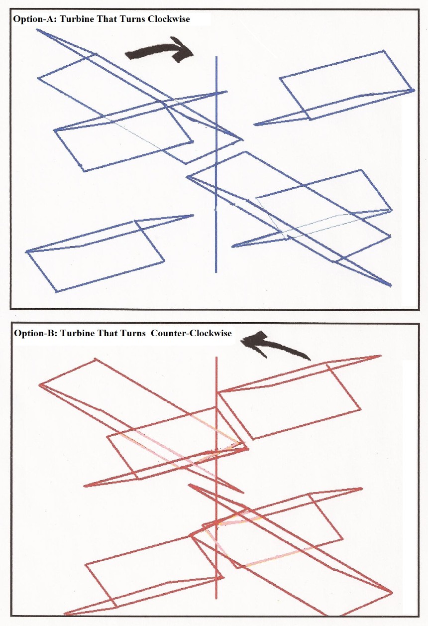
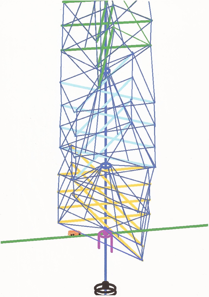
There shall be at least three different layers of clusters of V-type folding blades/frames within the whole tall turbine; and the said different layers are accurately set-up or distributed in particular angles in order to have uniformity of force vis-a-vis time or uniform force within a cycle of the turbine in running the generator. The angle between two adjacent outermost points of the top view of the wind turbine that has three layers is 30 degrees and is similar to the two adjacent outermost points in a clock like between 3 o'clock and 4 o'clock (See Illustration 1.). The 360 degrees of the whole spot are divided by 12 because each of the three layers have four outermost points like the outermost points of a cross or plus sign (+). The wind turbine that has four layers has 22.5 degrees (360 degrees divided by 16). The wind turbine that has five layers has 18 degrees (360 degrees divided by 20). The wind turbine that has six layers has 15 degrees (360 degrees divided by 24); and so on. The layers may be arranged by random as long as the 360 degrees in the top view are divided equally by the number of the outermost points but it is still better if everything is installed in a systematic way like a gradual twist as the assembly of different layers goes higher.
Illustration 1. The Perspective Of The Giant Wind Turbine That Is Carried By Wheels In Its Version With Only Three Layers (More Layers May Be Added.)
.jpg.opt860x1135o0,0s860x1135.jpg)
Every cluster of V-type folding blades/frames is operated by at least one pair of hydraulic cylinders that work for the synchronized closing and opening of the V-type folding blades/frames into particular angles in accordance with the maintained force. All hydraulic cylinders in the whole turbine have a synchronized activity.
Every cluster of V-type folding blades/frames is supported by a steel-reinforced base that is carried by cables or studs that are connected to a strong holder that is connected to the pole.
The leverage is better if the wind turbine is wider.
The frameworks and other parts of the giant wind turbine shall be constructed in accordance with the most efficient balance between lightness of weight and durability as well as with price and other things. If possible, the giant wind turbine shall be in its lightest possible weight but is in its toughest possible durability and also in the best price, safety, and other good things.
The layers of the clusters of V-type folding blade/frame in this wind turbine needs to be at least three; and it is better if it is made more than three and arranged basing on the equal division of the total angles in the circle, as can be seen in the top view, by the total number of arms of the turbine in order to have uniformity of force vis-a-vis time or uniform force within a cycle of the turbine in running the generator; and more blades are added. It is necessary that the blades are arranged in particular positions or angles that give a uniform force vis-a-vis time or uniform force within a cycle of the turbine in running the generator.
In accordance with the aim to generate electricity even in a very little amount of wind force, small generators are used in one turbine and the computer system that manipulate the hydraulics is used to run only one of the generators when there is a very little amount of wind force; and start the other generators one-by-one through computer-managed hydraulic clutch of each generator when the torque or "amount of twisting force" of the wind turbine, which is directly proportional to the amount of wind-force in normal circumstances, increases in particular levels that are enough to run two, three, four, or more generators respectively depending on the satisfaction of the torque-requirement of the generators. In this scenario, if the driveshaft where the clutch of the small generators are to be connected and/or disconnected is in Torque-Level 1, the computer that has control gadgets starts the generator for Torque-Level 1 by using the hydraulics to engage or connect the clutch of such generator; if the driveshaft where the clutch of the small generators are to be connected and/or disconnected is in Torque-Level 2, the computer that has control gadgets starts the generator for Torque-Level 2 by using the hydraulics to engage or connect the clutch of such generator, thereby making two generators running; if the driveshaft where the clutch of the small generators are to be connected and/or disconnected is in Torque-Level 3, the computer that has control gadgets starts the generator for Torque-Level 3 by using the hydraulics to engage or connect the clutch of such generator, thereby making three generators running; if the driveshaft where the clutch of the small generators are to be connected and/or disconnected is in Torque-Level 4, the computer that has control gadgets starts the generator for Torque-Level 4 by using the hydraulics to engage or connect the clutch of such generator, thereby making four generators running; if the driveshaft where the clutch of the small generators are to be connected and/or disconnected is in Torque-Level 5, the computer that has control gadgets starts the generator for Torque-Level 5 by using the hydraulics to engage or connect the clutch of such generator, thereby making five generators running; if the driveshaft where the clutch of the small generators are to be connected and/or disconnected is in Torque-Level 6, the computer that has control gadgets starts the generator for Torque-Level 6 by using the hydraulics to engage or connect the clutch of such generator, thereby making six generators running; if the driveshaft where the clutch of the small generators are to be connected and/or disconnected is in Torque-Level 7, the computer that has control gadgets starts the generator for Torque-Level 7 by using the hydraulics to engage or connect the clutch of such generator, thereby making seven generators running; and so on. If the whole turbine is set up to exclusively run an extremely big generator or a whole bunch of small generators with one synchronized action, the opportunity to make use of the relatively very low wind-force that is only enough to run one or two among the bunch of small generators is missed or wasted (This is like collecting gold only and exclusively when it is in a chunk form; and the one who collects the gold even those that are in a tiny powder particle form and also collects all chunks of gold gets more wealth.). In monitoring the torque of the long driveshaft that is the basis to accurately manipulate the engaging and disengaging of the clutch of the small generators, if the increase or decrease of the torque of the long driveshaft is directly proportional to the rounds-per-minute of the said long driveshaft in one particular fixed set-up of the whole turbine or site, then the rounds-per-minute of the said long driveshaft may serve as the basis for engaging or disengaging the clutch by the computer and its gadgets (Concerning the monitoring of the accuracy of the operation, the wind-speed data from the anemometer may be used as a tool if the torque of the particular turbine in a corresponding particular wind-speed is already accurately defined or calculated because this accurate definition or calculation may be used to detect if there is something wrong that stops the turbine and its connections or something wrong with the opening and closing of the V-type folding blades/frames; since, if the torque of the turbine is lower than the torque that accurately corresponds to a current wind-speed, it means that there is a problem that holds or stops the turbine and its connections or there may be a problem with the V-type folding blades that prevents them from harnessing wind-force. If the anemometer plays a crucial role in the operation of the system, the use of more than one anemometer, in which the highest number from among the anemometers is used, may help since the reliance on only one anemometer may give trouble if such solitary anemometer malfunctions.).
Illustration 2. The Small Generators And The Connections Of The Small Generators Of The Giant Wind Turbine That Is Carried By Wheels
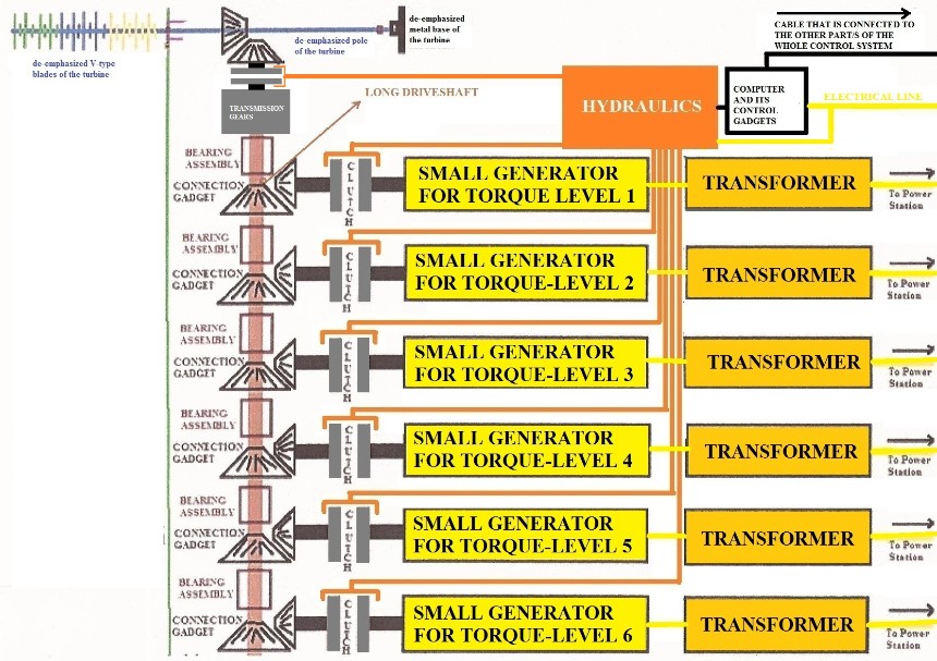
The cable that is connected to the other part/s of the whole control system is connected to the indicator for the rounds-per-minute (RPM) of the driveshaft or any monitored part as the basis for the sequential engagement or disengagement of the small generators. In this illustration, the giant wind turbine is twisted and de-emphasized. If the wind is relatively very weak, the giant wind turbine may still generate electricity because the small generator for Torque-Level 1 can be operated by a relatively very weak wind.
When the turbine is currently running many of the small generators and the force of the wind starts to decrease gradually, the clutch of the small generators that can no longer be supplied by rotational force due to said decreasing wind-force are disconnected or disengaged one-by-one as the wind-force decreases depending on the satisfaction of the force-requirement of the generators. If the generator for Torque-Level 3 can no longer be handled by the force, the clutch of such generator is disengaged. If the generator for Torque-Level 2 can no longer be handled by the force, the clutch of such generator is disengaged. If the generator for Torque-Level 1 can no longer be handled by the force, the clutch of such generator is disengaged. The "smallness" of the small generators shall be in the best small size to avoid wasting the small amounts of wind-force.
If the strength of the existing transmission box or boxes is/are not enough to facilitate additional generator/s in order to consume all the available energy from the turning giant wind turbine for efficiency, and/or if the strength of the gears that connect the transmission box to the pole are not enough to facilitate additional generator/s, additional transmission box/es may be installed to facilitate additional generator/s.
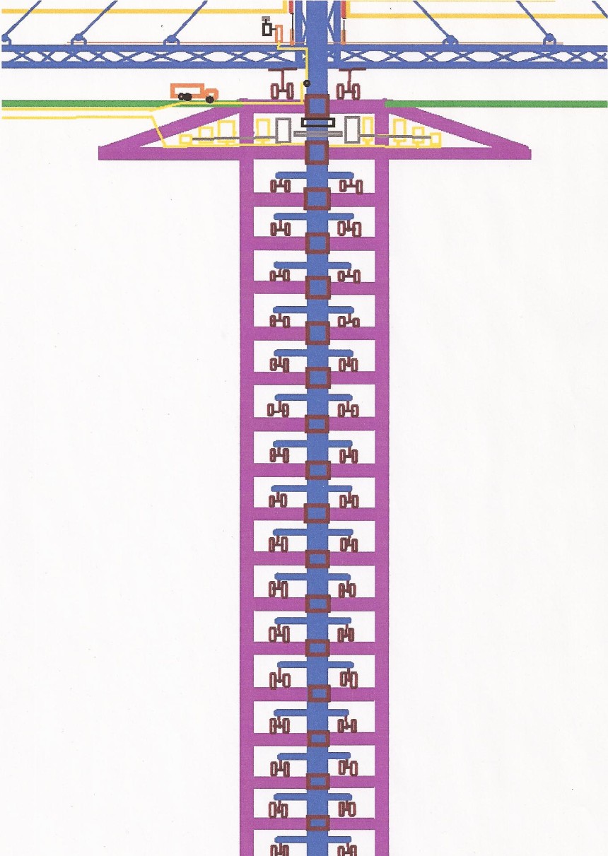
Illustration 3. The Addition Of More Transmission Boxes If Necessary
In a setting with more than one transmission boxes, separate clutch may be used to isolate the other transmission box/es when the torque of the pole of the turbine is not enough to run the additional transmission box/es; and such isolation is made one-by-one in accordance with the torque requirements of the transmission boxes like the manner in which the small generators are isolated and/or connected by disengaging and/or engaging the corresponding clutch.
The setting in the lower part of the giant wind turbine may be adjusted depending on the particular size of the turbine, the location of the turbine like on land or on sea, and other things in order to have the best or most efficient and safest setting for generating electricity.
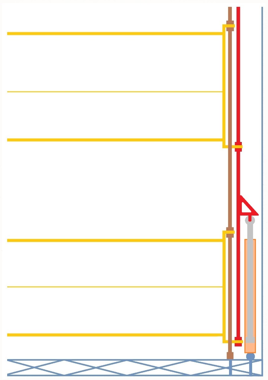
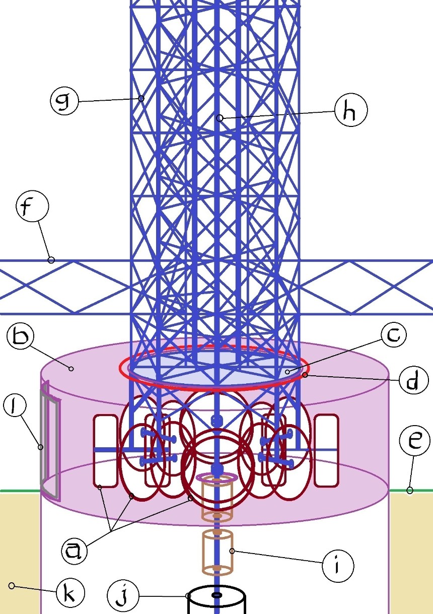
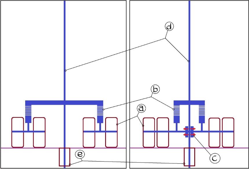
Illustration 4. The Side View Of The Lower Part Of The Giant Wind Turbine That Is Carried By Wheels In Its Version With Only Three Layers (This Illustration Is Also Applicable To All Other Versions With More Than Three Layers.)
..jpg.opt860x1076o0,0s860x1076.jpg)
Guide:
1. Computer That Uses Its Control Gadgets To Automatically Manage The Closing And Opening Of The V-Type Folding Blades Through Hydraulics
In Accordance With The Maintained Amount Of Force Whenever There Is A Remarkable Change Of Wind Speed
2. Motor And Pump And Other Gadgets For The Hydraulics
3. Hydraulic Cylinder
4. Gadget For The Synchronized Opening And Closing Of The V-Type Folding Blades Into An Angle That Is In Accordance With The
Maintained Amount Of Force
5. Lower Part Of The V-Type Folding Blade
6. Wind Speed Meter or Anemometer
7. Cable or Stud That Supports Base Of The Cluster Of V-Type Folding Blades
8. Strong But Relatively Light-Weight Wheels
8.1. Option-A: The Use Of Rubber Wheels
8.2. Option-B: The Use Of Metal Wheels
8.3. Other Option (If Any)
9. Bearing Assembly
10. Rotating Electrical Connection Mounted On The Pole
11. Cylindrical Fortified Ground To Carry The Weight Of The Whole Turbine
12. Connection Gadget
12.1. Option-A: The Use Of Gears
12.2. Option-B: The Use Of Industrial Belts
12.3. Other Option (If Any)
13. Transmission Gears
14. Small Generators
15. Electrical Line To Run The Computer System And The Hydraulics That Are Riding In The Turbine
16. Fortification Skeleton Tower
17. Upper Part Of The V-Type Folding Blade
18. Pole or Axis
19. Vertex Of The V-Type Folding Blade
20. Braking System For Safety And Maintenance
21. Transformers
22. Metal Bucket That Is Filled With Oil And Sealed (Optional Part [Warning: If there is a danger of igniting the oil inside the bucket, then there shall be no metal bucket and no oil but a strong flat thick bar or other strong material; and the pole may only touch such base during maintenance when such pole is not remarkably moving.])
23. Clutch
24. Driveshaft
OTHER PARTS (NOT REPRESENTED IN THE ILLUSTRATION):
25. Cooling Systems
25.1. Cooling System For The Bearings
25.1.1. Cooling System For The Bearings Of The Wheels
25.1.1.1. Option-A: The Use Of Water Spouts That Are Mounted Outside The Wheels
25.1.1.2. Option-B: The Use Of Water Spouts That Ride In The Axle-Frame Of The Wheels And
Supplied With Water Through Rotating Connections Between Water Lines
25.1.1.3. Other Option (If Any)
25.1.2. Cooling System For The Bearings Of The Pole
25.1.3. Cooling System For The Bearings Of The Long Driveshaft
25.1.4. Cooling System For Other Bearings (If Any)
25.2. Cooling System For The Joint Gears
25.3. Cooling System For The Transmission Gears
25.4. Cooling System For The Generator
25.5. Cooling System For The Metal Bucket That Is Filled With Oil (Optional Part [Warning: If there is a danger of igniting the oil inside the bucket, then there shall be no metal bucket and no oil but a strong flat thick bar or other strong material; and the pole may only touch such base during maintenance when such pole is not remarkably moving.])
25.6. Cooling System For Other Overheating-Prone Part/s (If Any)
26. Indicator For The Angle Of The V-Type Folding Blades
26.1. Option-A: By An Indicator For The Actual Synchronized Angle Of The V-Type Folding Blades
26.2. Option-B: By An Indicator For The Length Of Protrusion Of The Piston Rod Or Shaft Of The Hydraulic Cylinder
26.3. Other Option (If Any)
27. Compensation Gadget Between Rotating Or Turning Parts With Different Alignments
28. Indicator To Start The Cooling System For A Particular Part That Is Remarkably Running Or Is Threatened By Overheating
28.1. Option-A: The Use The Data On The Rounds-Per-Minute Of The Related Part
28.2. Option-B: The Use The Data On The Temperature Of The Related Part
28.3. Other Option (If Any)
29. Emergency Switch Located At Every Appropriate Corner Of The Site To Stop All Operations Immediately When Necessary
*If a gadget that uses magnetic levitation or anti-gravity (if really possible) can raise the wind turbine without consuming a remarkable amount of electricity or remarkable amount of wealth, and if this gadget has no remarkable disadvantage/s, then it may also be used to carry the wind turbine instead of wheels.
THE PARTS
1. Computer That Uses Its Control Gadgets To Automatically Manage The Closing And Opening Of The V-Type Folding Blades Through Hydraulics In Accordance With The Maintained Amount Of Force Whenever There Is A Remarkable Change Of Wind Speed
The computer system may include a radio-control system that links such computer system in the turbine to the computer system outside the turbine for emergency and maintenance purposes. Such radio-control system may also be used to automate the activity of the wind turbine through the data from the electrical output of the generator at the present moment (If the output goes on top of the maintained force, the computer system outside turbine uses the radio-control system to send the information to the computer system inside the turbine; and such computer system that rides in the turbine commands the hydraulics system to close the blades of the turbine into particular angles in accordance with the maintained amount of force. The radio-control system outside the turbine may also be manually activated to command the computer system that rides in the turbine to totally close all the blades of the turbine when a tornado travels straight towards the said turbine in order to prevent damage.).
Through the use of computer system inside the turbine, the entire power plant can be supervised, monitored, controlled, and/or operated remotely or like the way that an unmanned aerial vehicle is operated. If the giant wind turbine that designed to harness a greater amount of wind-force is not made to automatically close when there is an excessive force from the wind like in a hurricane, such giant wind turbine is closer to possible destruction.
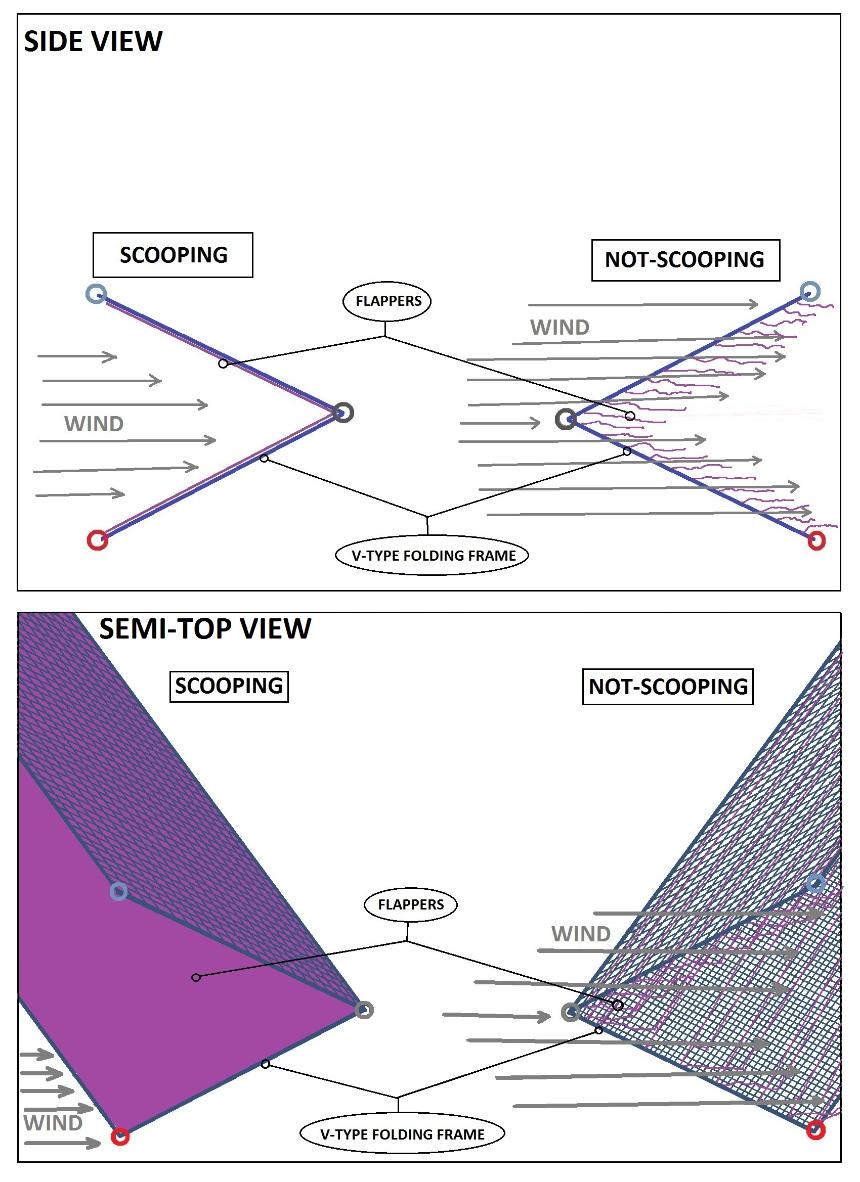
Illustration 5. The Wind-Harnessing Mechanism Of The Giant Wind Turbine That Is Carried By Wheels
The form that is highly recommended is the one that uses valve-like flappers that are made up of durable thin polyethylene plastic sheets because this form increases the collection of force since there is no or almost no air resistance when the V-type folding blade/frame is not scooping. When the V-type folding blade/frame is not scooping, the durable thin polyethylene plastic sheets are flying freely in the air; but when the V-type folding blade/frame is scooping, the durable thin polyethylene plastic sheets are pressed by the wind against the thin-but-strong screen of the V-type folding blade/frame that is tightened or hardly stretched like a screen of badminton racket and form an excellent scoop or wind-catcher (The thin polyethylene plastic sheets are very light to be blown by the wind so they react too quickly to the changes of wind action as the wind turbine rotates [Anything that is equal or better than polyethylene plastic sheet may also be used.]. In addition, the use of durable thin polyethylene plastic sheets as valve-like flappers may be better because their extremely light weight that is combined with light-weight thin screen is much better for weight reduction if compared to the use of wood or galvanized iron as not-flapping "flesh" for the V-type folding blades/frame.). Another advantage of the this form that uses valve-like flappers that are made up of durable thin polyethylene plastic sheets is that the V-type folding blade/frame can open into a wider angle that may even reach almost 180 degrees because there is no or almost no air resistance if the V-type folding blade/frame is not scooping since the very light polyethylene plastic sheets are flying freely in the air when the V-type folding blade/frame is not scooping; and during the occurrence of destructive hurricane winds, the V-type folding blade/frame will simply close into a very sharp angle that is in a lying-flat horizontal position to avoid scooping excessive wind-force.
Illustration 5.2.1. The Highly Recommended Form That Uses Durable Thin Polyethylene Plastic Sheets As Valve-Like Flappers
2. Motor And Pump And Other Gadgets For The Hydraulics
The motor and pumps and other gadgets for the hydraulics shall be the lightest ones or not-heavy as long as they can efficiently close and open the blades in accordance with the maintained force whenever there is a remarkable change of wind speed.
If the wind turbine is very tall, there may be more than one motor and pump; and all the motors and pumps may have a synchronized switch.
3. Hydraulic Cylinder
The hydraulic cylinders shall be the lightest ones or not-heavy as long as they can efficiently close and open the blades in accordance with the maintained force whenever there is a remarkable change of wind speed.
Illustration 6. An Ideal Position Of The Hydraulic Cylinder In The Cluster Of V-Type Blades To Save Space
The maximum protrusion of the shafts or rods of the hydraulic cylinders may be set to be at the point that is also the fully-closed condition of the V-type folding blades in order to prevent wrecking a related part in case of malfunction of the control system or any related malfunction.
In reducing the idle weight of the wind turbine, the hydraulic cylinders may also be put at the upper part of the cluster in order to have a pulling force of the rods/pipes when closing the V-type folding blades because a very thin rod/pipe will not fold or bend when it is pulled from the upper point or tip of such rod/pipe. A very thin rod/pipe may fold or bend when it is pushed by the hydraulic cylinder from the lower point or tip of such rod/pipe that is located at the bottom of the cluster of V-type folding blades. A thicker or bigger rod/pipe means a heavier weight; and a thinner or smaller rod/pipe means a lighter or lesser weight. However, a hydraulic cylinder at the upper part of the cluster also requires additional metal structure for its foundation. The difference may be calculated and the durability and other things shall be considered; and the one that is better in the bottom line shall be used.
An arrangement that is better in idle-weight reduction is the one that has no or almost no gap between the V-type folding blades because it requires much lesser pieces of steel or other materials for support and for the synchronization of operation since there is no or almost no gap to fill (See Illustration 6.1.). Every layer of cluster in this idle-weight-reducing arrangement is composed of only one pair of clusters of V-type folding blades and it can be seen as a straight line if viewed from the top. The minimum number of layers of clusters of V-type folding blades in this idle-weight-reducing arrangement is six in order to form the minimum angle between the outermost points of the top view of the wind turbine that is 30 degrees, which is for the uniformity of force vis-a-vis time or uniform force within a cycle of the turbine in running the generator (See Illustration 6.1.). This idle-weight-reducing arrangement also requires at least one pair of hydraulic cylinders per cluster (If hydraulics technology is not available in a place, or if preferred, the use of pulley or other related things may also be used to close and open the V-type folding blades. In a setting that uses polyethylene plastic sheet flappers or other light-weight flappers, if there is a malfunction of hydraulics or the related gadget for closing the V-type folding blades, and if there is an immediate need to close the V-type folding blades to avoid destruction, another option to avoid harnessing a destructive amount of force is to remove the polyethylene plastic sheets and/or other flappers. This option also makes it possible that there is no need to install hydraulics or other related gadgets in the wind turbine – just manually remove the polyethylene plastic sheets and/or other flappers when necessary to avoid destruction by excessive force; and in this setting, there is no need for V-type folding blades/frames [The V-type folding blades/frames is just necessary for the automation of the wind turbine in this regard.].).
Illustration 6.1. The Arrangement Of V-Type Folding Blades And Their
Clusters That Is Better In Idle-Weight Reduction
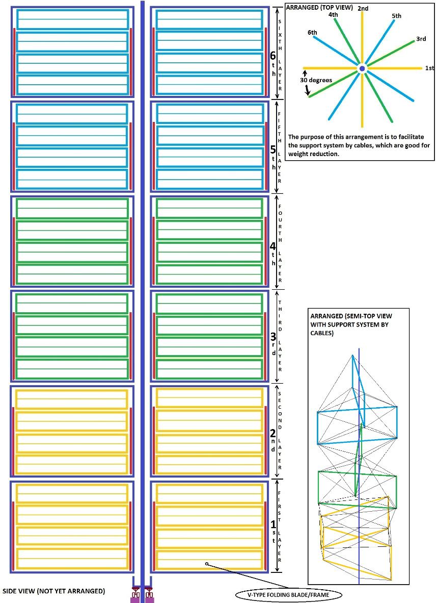
What is reduced in this arrangement is the idle weight or the weight that is not used or just a waste or just an additional weight that consumes wind force. In this arrangement, the whole turbine becomes taller and heavier but the idle weight is reduced.
An alternative for the V-type folding blade/frame that may be better in idle-weight reduction is the use of roller that hides the light-weight flapper during the times of excessive wind force (See Illustration 6.2.). In this setting, there is no V-type folding blade/frame but simply a vertical 180-degree tightened screen. The only heavier materials to be used are the gadgets to safely roll to hide the light-weight flapper when there is excessive wind force and unroll to expose the light-weight flapper when the wind force becomes weaker.
Illustration 6.2. The Alternative For The V-Type Folding Blade That May Be
Better For Idle-Weight Reduction
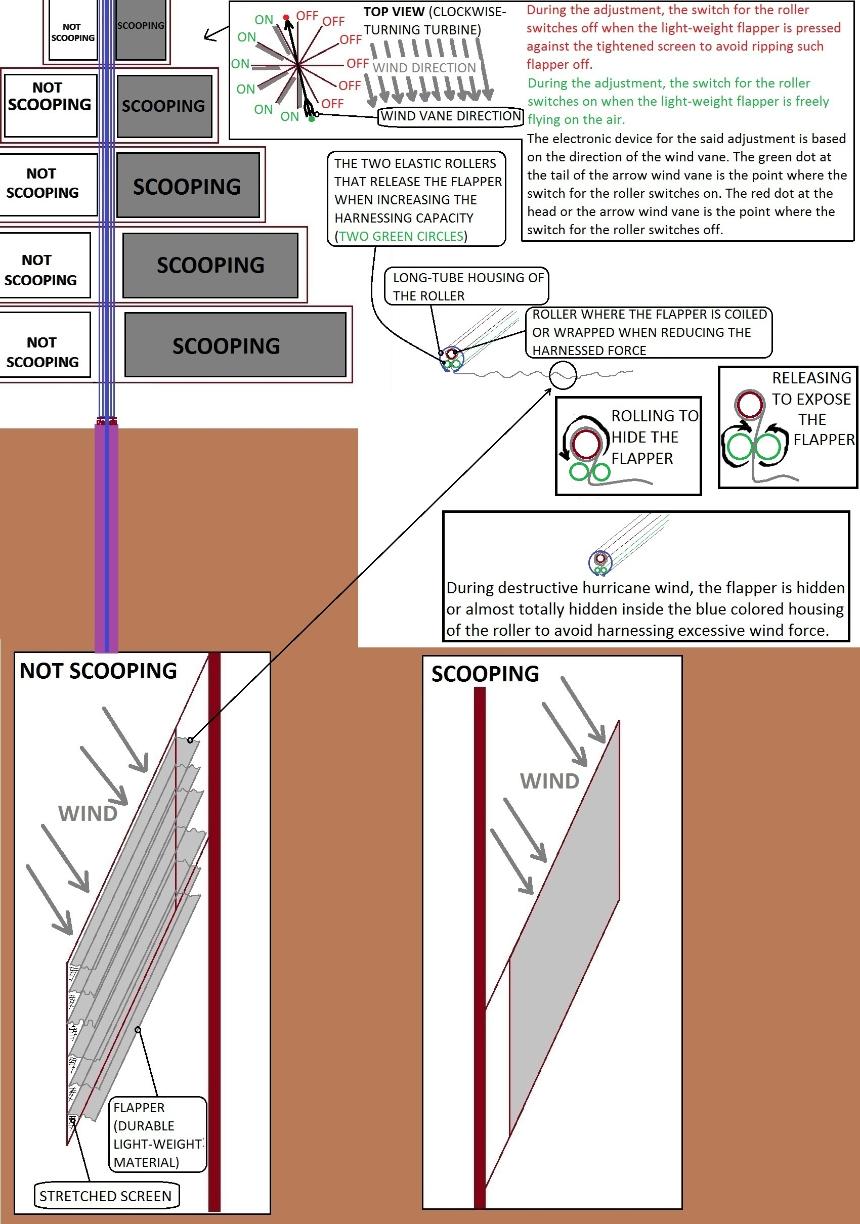
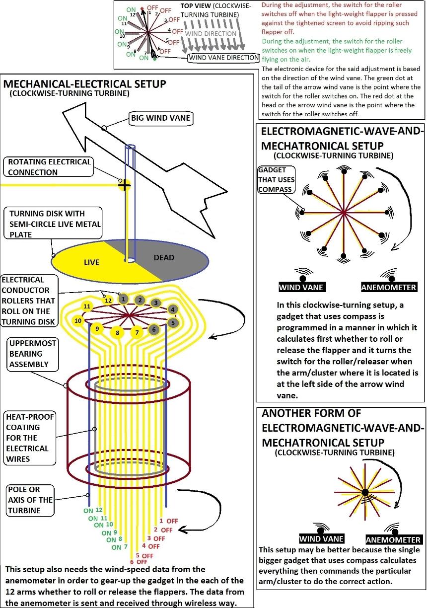
In this alternative, the device for the adjustment for the increase or decrease of wind-harnessing capacity by rolling or releasing the flappers may use mechanical-electrical, electromagnetic-wave-and-mechantronical, and/or other setup/s that may be equal to, or better than, the said setups (See Illustration 6.3.).
Illustration 6.3. Conceptual Setups For The Automated Rolling Or Releasing
Of The Valve-like Flappers
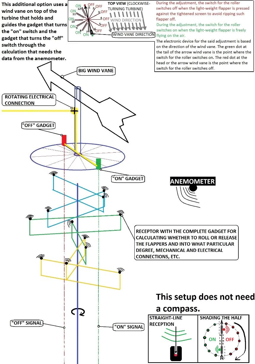
Another option is the one that has a wind vane on top of the turbine that holds “’on’ gun” and “’off’ gun” (Illustration 6.3.1.).
Illustration 6.3.1. Additional Option For The Conceptual Setups For The
Automated Rolling Or Releasing Of The Valve-like Flappers
4. Gadget For The Synchronized Opening And Closing Of The V-Type Folding Blades Into An Angle That Is In Accordance With The Maintained Amount Of Force
Every layer of cluster of V-type folding blade has a separate gadget for the synchronized opening and closing of the blades into an angle that is in accordance with the maintained force.
The gadget for the synchronized opening and closing of the blades into an angle that is in accordance with the maintained force plays a very important function during the occurrence of a hurricane or very strong wind. The V-type folding blades are closed into smaller angle during the occurrence of a hurricane or very strong wind. Without this gadget, the whole turbine is exposed to harnessing excessive wind force during the occurrence of a hurricane or very strong wind and this leads to the destruction of the turbine.
The mechanism of the synchronized opening and closing of the V-type folding blades has a similarity with the opening and closing of the multi-bladed window or the window blind of house but the V-type folding blades are closed like human elbows that are pushed back. In synchronizing movements, all the V-type folding blades in a cluster are connected to a pair of movable long metal round bars or pipes located at both ends or sides of the cluster. Whenever the round bars or pipes are pushed by the hydraulics, all the V-type folding blades also move.
Important: In reinforcing or making gadgets for the wind-exposed part of the turbine, avoid using wide flat bar, I-bar, or any material that scoops a remarkable amount of wind force to prevent the destruction of the turbine during hurricane or destructive winds (Flat bars or I-bars may be used as long as their sizes do not scoop a remarkable wind-force or as long as they are assembled or welded into a form that eludes wind-force.). Cable is a good material to reinforce the turbine like reinforcing a suspension bridge and sideward because cable eludes wind-force. All materials that are not intended to scoop wind shall be installed in a way that eludes wind force to prevent the destruction of the wind turbine.
Illustration 7. Gadget For Synchronized Opening And Closing Of The V-Type Folding Blades
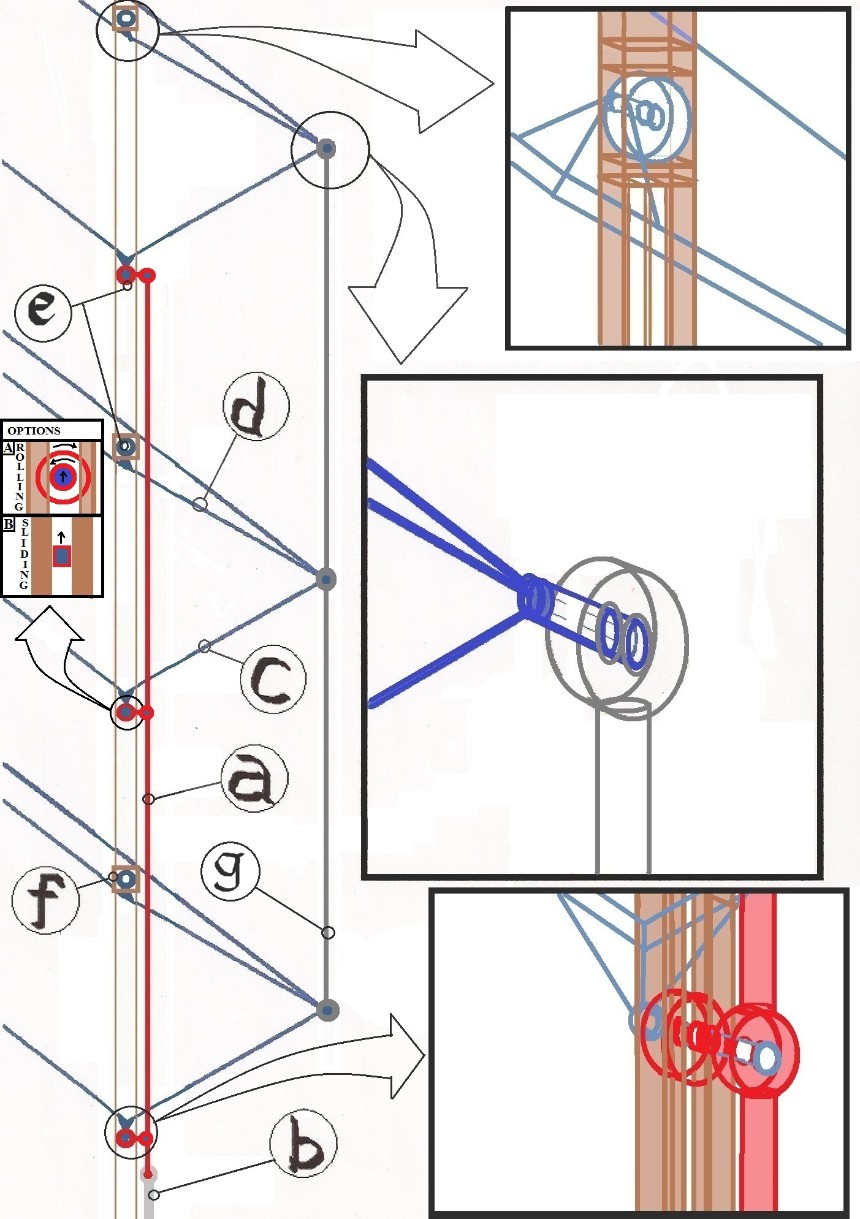
Guide: a) connecting round bar or pipe that holds the corners of the lower parts of the V-type folding blades for a synchronized closing or opening, b) rod or shaft of the hydraulic cylinder, c) metal frame of the lower part of the V-type folding blade, d) metal frame of the upper part of the V-type folding blade, e) turning joints, f) fixed frame that holds the corner of the upper parts of the V-type folding blades, g) round bar or pipe that support the vertices of the V-type folding blades. In order to have a perfect closing or fitting of the V-type folding blades, the turning joints that connect the metal frames of the V-type folding blades to the connecting round bars or pipes shall not hit each other.
IMPORTANT: The gap or distance between two adjacent vertices of V-type folding blades needs to be twice the height of a fully opened V-type blade in its "maximum-wind-harnessing-but-has-the-maximum-capability-to-elude-wind-when-not-scooping" angle that is the best angle (The best angle is almost 180 degrees if the polyethylene plastic flappers are used as the “flesh” for the V-type folding blade/frame. The presence of the support rod/pipe for the vertices of the V-type folding blades/frames leave an inclination that makes it easier for the hydraulics to bend or close the V-type folding blades/frames when necessary. ). The vertex of one V-type folding blade (Blade-A) needs to be at a level that is higher or lower than the level of the vertices of the closest V-type folding blades that are in the other arms or other sides of the particular layer of the turbine and are perpendicular to Blade-A; and the level of the vertex of Blade-A is higher or lower at a distance that is twice the gap between two adjacent vertices (See Illustration 4.). The purpose of this is to avoid blocking a currently scooping V-type folding blade from harnessing wind force (The number of V-type blades in one cluster may be increased as long as the hydraulic cylinders can push to close them efficiently.). However, this arrangement allows additional/waste weight or idle weight because of the longer length of connecting support rods or pipes and other pieces of metal that passes through the longer gaps between the V-type folding blades in one cluster. An arrangement that is better in idle-weight reduction is the one that has no or almost no gap between the V-type folding blades because it requires much lesser pieces of steel or other materials for support and for the synchronization of operation since there is no or almost no gap to fill (See Illustration 6.1.). Every layer of cluster in this idle-weight-reducing arrangement is composed of only one pair of clusters of V-type folding blades and it can be seen as a straight line if viewed from the top. The minimum number of layers of clusters of V-type folding blades in this idle-weight-reducing arrangement is six in order to form the minimum angle between the outermost points of the top view of the wind turbine that is 30 degrees, which is for the uniformity of force vis-a-vis time or uniform force within a cycle of the turbine in running the generator (See Illustration 6.1.). This idle-weight-reducing arrangement also requires at least one pair of hydraulic cylinders per cluster (If hydraulics technology is not available in a place, or if preferred, the use of pulley or other related things may also be used to close and open the V-type folding blades. In a setting that uses polyethylene plastic sheet flappers or other light-weight flappers, if there is a malfunction of hydraulics or the related gadget for closing the V-type folding blades, and if there is an immediate need to close the V-type folding blades to avoid destruction, another option to avoid harnessing a destructive amount of force is to remove the polyethylene plastic sheets and/or other flappers. This option also makes it possible that there is no need to install hydraulics or other related gadgets in the wind turbine – just manually remove the polyethylene plastic sheets and/or other flappers when necessary to avoid destruction by excessive force; and in this setting, there is no need for V-type folding blades/frames [The V-type folding blades/frames is just necessary for the automation of the wind turbine in this regard.].).
The sizes, the width-length proportions, and the numbers of the V-type folding blades in one cluster may be increased or decreased or modified in accordance with the best possible form and condition of this wind turbine that considers weight reduction, durability, variations of wind direction, manageability by hydraulics or other manipulating gadgets, and other related things (The purpose of showing extremely big V-type folding blades in Illustration 4 is to elaborate the design for the mechanical operations [Also, any other part in the illustrations in this presentation that is extremely big or disproportionate is shown in such manner in order to elaborate the design or elaborate the representation or symbolism. In this giant wind turbine, everything shall be in the perfect form and condition.].).
In making the V-type folding blades lighter in weight, the wide and thin boards of the light-weight kind of wood/timber/lumber may be used to be clipped or mounted on the metal frames of the V-type folding blades. If there is too much supply of timber, the turbine may be much cheaper (Another option is the use of thin and light but strong plastic sheets. Also, another option is the use of galvanized iron sheets but it may be very noisy. If nobody will be disturbed by the noise in the sea, then the noisy blades may be used in the sea or in the offshore wind farms. Anything that may be equal or better to the aforesaid materials may be used; and the best material for a particular location may be preferred.).
The form that is highly recommended is the one that uses valve-like flappers that are made up of durable thin polyethylene plastic sheets because this form increases the collection of force since there is no or almost no air resistance when the V-type folding blade/frame is not scooping. When the V-type folding blade/frame is not scooping, the durable thin polyethylene plastic sheets are flying freely in the air; but when the V-type folding blade/frame is scooping, the durable thin polyethylene plastic sheets are pressed by the wind against the thin-but-strong screen of the V-type folding blade/frame that is tightened or hardly stretched like a screen of badminton racket and form an excellent scoop or wind-catcher (The thin polyethylene plastic sheets are very light to be blown by the wind so they react too quickly to the changes of wind action as the wind turbine rotates [Anything that is equal or better than polyethylene plastic sheet may also be used.]. In addition, the use of durable thin polyethylene plastic sheets as valve-like flappers may be better because their extremely light weight that is combined with light-weight thin screen is much better for weight reduction if compared to the use of wood or galvanized iron as not-flapping "flesh" for the V-type folding blades/frame.). Another advantage of the this form that uses valve-like flappers that are made up of durable thin polyethylene plastic sheets is that the V-type folding blade/frame can open into a wider angle that may even reach almost 180 degrees because there is no or almost no air resistance if the V-type folding blade/frame is not scooping since the very light polyethylene plastic sheets are flying freely in the air when the V-type folding blade/frame is not scooping; and during the occurrence of destructive hurricane winds, the V-type folding blade/frame will simply close into a very sharp angle that is in a lying-flat horizontal position to avoid scooping excessive wind-force.
6. Wind Speed Meter or Anemometer
The wind speed meter or anemometer measures the speed of the wind and the data is sent to the computer system. The computer system commands the activities of the motor and pumps and other gadgets for the hydraulics that open and close the blades into a particular angle in accordance with the maintained amount of force whenever there is a remarkable change of wind speed.
The wind speed meter or anemometer may also be installed outside the turbine like on top of the fortification tower and send the data to the computer that controls the hydraulics through radio-control system (Another way to monitor excessive wind is by monitoring the activity of the smalls generators. When all the small generators are already running and the electrical output goes beyond the designated limit, if any, the data about such excess that is monitored by a computer outside the turbine is sent to the computer that rides in the turbine; and such computer that rides in the turbine commands the hydraulics to close the V-type folding blades.).
7. Cable or Stud That Supports Base Of The Cluster Of V-Type Folding Blades
The action of the cable or stud that supports the base of a particular cluster of V-type blades is similar to the action involved in the suspension bridge. Illustration 4 shows only four cables or studs but more can be added for a greater support. Also, Illustration 4 does not show a heavily fortified holder at the upper part of the pole. If the base of the turbine is too heavy, the holder that carries the cables or studs and supports the base of a particular cluster of V-type folding blades shall be fortified into solid metal that is mounted well on the pole of the turbine.
If the wind turbine stands on a place that is prone to strong winds that push upwards like when the turbine stands on top of a hill, additional cables or studs may also be installed in an inversed way to support the cluster of V-type folding blades from being blown upwards. The inversed way is by connecting one of the ends of the cable or stud at the bottom of the base of the cluster then connect the other end of such cable or stud to the pole below the cluster and form 45 degrees downward or around such angle as long as the support strength is good.
The cables may also play a key role in lessening the weight of the turbine because instead of using heavy reinforcement bars to support the lower beams or base of the clusters of V-type folding blades, cables may be used to reinforce such beams by hanging them to the pole or to any point/direction that can give the best strength and lightest possible weight of the turbine.
Illustration 8. Conceptual Support System By Cables To Avoid Using Heavy And Wind-Scooping Materials
If a gadget that uses magnetic levitation or anti-gravity (if really possible) can raise the wind turbine without consuming a remarkable amount of electricity or remarkable amount of wealth, and if this gadget has no remarkable disadvantage/s, then it may also be used to carry the wind turbine instead of wheels.
The wheels shall be constructed in accordance with the most efficient balance between strength and lightness of weight as well as with price and other things. If possible, the wheels shall be in their strongest possible capability to carry the whole turbine but are in their lightest possible lower weight and with the cheapest price and best conditions.
During the wind-harnessing action, the strong but light wheels may be the sole carrier of the turbine, may be the main carrier of the turbine, or may be the secondary carriers or helpers for the metal bucket that is filled with oil (If it is better to make the wheels as the sole carrier of the turbine during wind-harnessing action and there is a gap between the pole and the metal bucket, then there is no need for a metal bucket since the purpose of the metal bucket is to contain oil to lubricate the friction between the pole and the metal surface. If the wheels are designed to carry the whole turbine during wind-harnessing action and there is a gap between the pole and the metal bucket, a thick flat metal wider bar that sits on a strong foundation is enough to carry the pole that carries the whole turbine during maintenance when the wheels are removed (However, it may still be safer to put a metal bucket that is filled oil below the pole even if the wheels are the sole carriers of the turbine during wind-harnessing action because there is always a possibility that the wheels may break down and make the bottom of the pole have contact with the metal below and create a destructive friction.). If it is good to make the metal bucket as the secondary carrier that gets some of the weights during wind-harnessing action, then it needs to be lubricated. If there is no problem on giving the weight of the whole turbine to the metal bucket that is filled with oil during wind-harnessing action, then the said metal bucket that is filled with oil shall be made as the main carrier of the whole turbine during wind-harnessing action; and the edge of the pole that touches the metal bucket may be made pointed to lessen friction [The use of oil inside the bucket is to prevent damage from the friction. The metal bucket needs to be covered and sealed to prevent water from mixing with the oil since water goes at the bottom where there is friction and may cause damage.].).
The leverage is better if the wheels are closer to the pole or axis of the turbine.
Considering the exposure of the bearings of the wheels into possible continuous frictionful duty, the wheels need to be designed in a way that is very easy to dismantle for an efficient regular check-up or maintenance. A cooling system for the wheels like the use of water that continuously circulates and automatically pours water with pressure on the bearing housings of the wheels whenever the turbine runs may also be used (Computer can automate the whole system even the pouring of water with pressure on the bearing housings of the wheels whenever the turbine runs remarkably. If it is impossible to put water ducts in the housings of bearings of the wheel, then the cooling system needs to be the use of water that is poured with pressure and circulates through filtered tank and pump below the floor level of the pathway of the wheels; in such case, this cooling system outside the turbine pour water with pressure on the bearing housings whenever the turbine runs remarkably; and the water circulates and reused through the use of the slits of the floor and little dikes, which surround the pathway of the wheels, and is combined with filters, tank, and water pump. The computer system in the basement can automate the all the cooling systems in the whole site (The cooling system for the bearing housings of the wheels can also be triggered by the movement of the pole or other stimulus below the first layer of clusters of V-type blades.). Even the level of water in the filtered container that is poured with pressure to the housings of the bearings of the wheels and circulates, which is gradually consumed by evaporation, can be monitored by the computer through a floating indicator; and everything in the power plant can be monitored and manipulated remotely or like the way that an unmanned aerial vehicle is operated.).
Important: If the wheels above the cylindrical fortified ground (Part No. 11) are not enough to carry the whole turbine like in the case of addition of many more layers of clusters of V-type blades that makes the turbine much taller, a fortified floor may be installed around the bearing assembly that is located just on top of the braking system (Part No. 20) and simply add another set of wheels that stand on this fortified floor; and such additional set of wheels can help in carrying the turbine through strong beams that are attached to the pole. If the said fortified floor is still not enough, another fortified floor may be installed around the bearing assembly that is located just on top of the metal bucket (Part No. 22) and simply add another set of wheels that stand on this fortified floor; and such additional set of wheels can help in carrying the turbine through strong beams that are attached to the pole. If the two aforesaid fortified floors are still not enough, a set of wheels may be put around the metal bucket (Part No. 22); and such additional set of wheels can help in carrying the turbine through strong beams that are attached to the pole. If these three additional levels of sets of wheels are still not enough, the solution is to simply keep on making additional fortified floor/s in the most appropriate point/s below the connection gadget (Part No. 12). Such additional fortified floor/s shall be below the connection gadget (Part No. 12) in order to make the said connection gadget (Part No. 12) closer to the beam of base of the first layer of clusters of blades to cope up with the twisting force from the turbine (To cope up with the twisting force from the turbine, the braking assembly may also be installed just below next to the rotating electrical connection [Part No. 10]; and this rotating electrical connection shall be as close as possible to the bottom of the highest wheels in order to adjust the braking system [Part No. 20] and the connection gadget [Part No. 12] closer to the base of the first layer of clusters of V-type blades [The rotating electrical connection {Part No. 10} may even be installed in the level just below the base of the first layer of clusters of V-type folding blades and the electrical line or cable {Part No. 15} can pass through a metal pipe that runs through the floor under the wheels that are connected to the base of the first layer of clusters of V-type folding blades [See Illustration 9.].). The part of the pole between the base of the first layer of cluster of V-type folding blade and the connection gadget [Part No. 12] that contain the forceful braking system shall be well fortified because a great twisting force is exerted in this point [The braking system in the pole may also be helped by putting brakes on the wheels.].). For lateral strength, a bearing assembly that does not affect the strength of the pole may be added for every additional fortified floor. Any wheel shall not stand too far from the pole to have an excellent leverage (Also, the width of the turbine shall be increased into the best proportion if the turbine is designed to be higher in order to have the best bottom-line efficiency; and the increase of width of the turbine may require the addition of cables or studs that support the bases of the layers of clusters of V-type folding blades in a manner that is like the way the cables or studs support a suspension bridge. The cooling systems for all the additional wheels, when such wheels are needed, have the same setting as the wheels above the cylindrical fortified ground (The entry of water inside the metal bucket shall be avoided.).
There is no problem on the noise in using metal wheels in the basement since they are sealed underground to prevent the sound from going out.
Illustration 9. The Side View Of The Lower Part Of The Giant Wind Turbine That Is Carried By Wheels In Its Version With Too Many Layers
There is no problem on the noise in using metal wheels in the basement since they are sealed underground to prevent the sound from going out. Metal wheels may also be silenced even outside the ground by putting a sound-proof enclosure around the wheels (when they are placed at the highest level of cluster of wheels outside the ground).
8.1. Option-A: The Use Of Rubber Wheels
If the wheels are the sole carrier of the turbine during wind-harnessing action, the weight of the turbine can be loaded on the rubber wheels by raising the turbine with big hydraulics then tightening the screw or stretching part that connects the turbine and the rubber wheels. The frame where the wheels are attached may also have their own hydraulic systems. Any better way may be used.
Considering the exposure of the bearings of the wheels into possible continuous frictionful duty, the wheels need to be designed in a way that is very easy to dismantle for an efficient regular check-up or maintenance. A cooling system for the wheels like the use of water that continuously circulates and automatically pours water with slight pressure on the bearing housings of the wheels whenever the turbine runs may be used (Computer can automate the whole system even the pouring of water on the bearing housings of the wheels whenever the turbine runs remarkably.).
The rubber wheels are more silent than the metal wheels.
Rubber wheels may be made more silent by putting a soundproof enclosure around the wheels (when they are placed at the highest level of cluster of wheels outside the ground). However, in the offshore setting, there may be no problem on silencing or muffling the rubber wheels.
Illustration 9.1. Soundproof Enclosure For The Uppermost Wheels Of The Giant Wind Turbine
Guide: a) wheels, b) soundproof enclosure, c) rotating cap of the soundproof enclosure, d) rolling or sliding sealer for the gap between the soundproof enclosure and its rotating cap, e) ground surface level, f) the base of the lowest cluster of V-type folding blades, g) support that helps in carrying the weight of the upper part of the turbine, h) pole or axis, i) bearing assembly, j) braking system - Braking system may also be put on the wheels, k) underground level, l) sealable soundproof door
8.2. Option-B: The Use Of Metal Wheels
If the wheels are the sole carrier of the turbine during wind-harnessing action, the weight of the turbine can be loaded on the rubber wheels by raising the turbine with big hydraulics then tightening the screw or stretching part that connects the turbine and the rubber wheels. The frame where the wheels are attached may also have their own hydraulic systems. Any better way may be used.
Considering the exposure of the bearings of the wheels into possible continuous frictionful duty, the wheels need to be designed in a way that is very easy to dismantle for an efficient regular check-up or maintenance. A cooling system for the wheels like the use of water that continuously circulates and automatically pours water with slight pressure on the bearing housings of the wheels whenever the turbine runs may be used (Computer can automate the whole system even the pouring of water on the bearing housings of the wheels whenever the turbine runs.).
The metal wheels produce more sound than the rubber wheels.
Metal wheels may also be silenced even outside the ground by putting a soundproof enclosure around the wheels (when they are placed at the highest level of cluster of wheels outside the ground). However, in the offshore setting, there may be no problem on silencing or muffling the metal wheels.
8.3. Other Option (If Any)
Anything that may exist that has the same efficiency or better than Option-A and Option-B may be used.
Illustration 9.2. Two Ways Of Putting The Weight Of The Pole On The Wheels
Guide: a) wheels, b) adjustable or stretchable gadget that may use hydraulics that puts the weight of the pole on the wheels, c) bolts and nuts assembly, d) pole, e) bearing assembly
9. Bearing Assembly
Bearing assemblies are used to hold the pole. The diameter of the center hole of the biggest possible size of bearing may not be big enough to allow the pole to be inserted inside such center hole. In case the bearings are smaller, one possible remedy is to make an assembly of bearings that surround the large circumference of the pole; and the bearings are like rolling around the pole.
More layers of bearing assemblies may be added on top of the turbine if the turbine is designed to be higher or bigger.
Bearing assemblies are also used to hold the long drive shaft.
Illustration 10. Two Options For Designing The Bearing Assembly
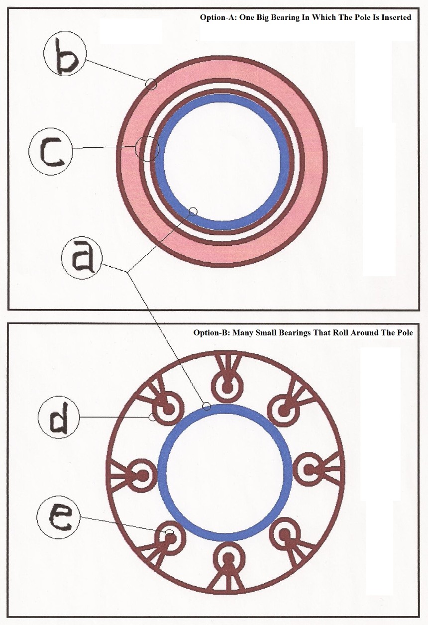
Guide: a) pole, b) the outermost part of the one big bearing, c) the innermost ring of a bearing, d) the outermost part of one of the small bearings, e) the innermost ring of one of the small bearings
If the wind turbine is very tall, bearing assembly may also be installed at the middle part of the height of the pole for a better support.
Illustration 10.1. Bearing Assembly At The Middle Part Of The Height Of The Pole
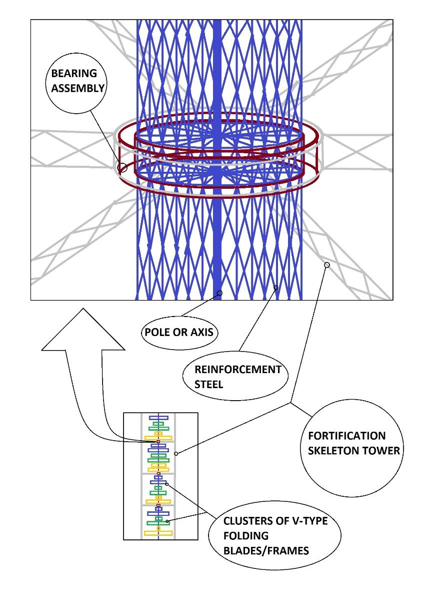
The connection needs to be rotating or has similarity to the action between the brush and the commutator inside the motor because if not, the electrical wire outside the pole will be pulled or winded by the turning pole.
11. Cylindrical Fortified Ground To Carry The Weight Of The Whole Turbine
The pole runs exactly at the center of the hole of the cylindrical fortified ground.
The cylindrical fortified ground shall be constructed in accordance with the most efficient balance between durability and price. If possible, the cylindrical fortified ground shall be in its strongest possible fortification but is in its cheapest possible low-price.
12. Connection Gadget
The connection gadget may use gears or industrial belts.
If there is a problem on misalignment or lateral movement or other movement of the pole or other related turning parts, universal joints or other compensation parts may be used.
The connection gadget may be found in many parts of the whole site.
12.1. Option-A: The Use Of Gears
Connection gadgets that use gears may be manufactured purposely for this wind power plant and in accordance with the calculations for this wind power plant. Gears from big trucks or machines may also be used (or recycled if taken from used or junked big trucks/machines).
12.2. Option-B: The Use Of Industrial Belts
Connection gadgets that use industrial belts may be manufactured purposely for this wind power plant and in accordance with the calculations for this wind power plant. Industrial belts from big machines may also be used (or recycled if taken from used or junked machines).
12.3. Other Option (If Any)
Anything that may exist that has the same efficiency or better than Option-A and Option-B may be used.
13. Transmission Gears
Transmission gears may be manufactured purposely for this wind power plant and in accordance with the calculations for this wind power plant. Transmission gears from big trucks may also be used (or recycled if taken from used or junked big trucks).
14. Small Generators
In accordance with the aim to generate electricity even in a very little amount of wind force, small generators are used in one turbine and the computer system that manipulate the hydraulics is used to run only one of the generators when there is a very little amount of wind force; and start the other generators one-by-one through computer-managed hydraulic clutch of each generator when the torque or "amount of twisting force" of the wind turbine, which is directly proportional to the amount of wind-force in normal circumstances, increases in particular levels that are enough to run two, three, four, or more generators respectively depending on the satisfaction of the torque-requirement of the generators. In this scenario, if the driveshaft where the clutch of the small generators are to be connected and/or disconnected is in Torque-Level 1, the computer that has control gadgets starts the generator for Torque-Level 1 by using the hydraulics to engage or connect the clutch of such generator; if the driveshaft where the clutch of the small generators are to be connected and/or disconnected is in Torque-Level 2, the computer that has control gadgets starts the generator for Torque-Level 2 by using the hydraulics to engage or connect the clutch of such generator, thereby making two generators running; if the driveshaft where the clutch of the small generators are to be connected and/or disconnected is in Torque-Level 3, the computer that has control gadgets starts the generator for Torque-Level 3 by using the hydraulics to engage or connect the clutch of such generator, thereby making three generators running; if the driveshaft where the clutch of the small generators are to be connected and/or disconnected is in Torque-Level 4, the computer that has control gadgets starts the generator for Torque-Level 4 by using the hydraulics to engage or connect the clutch of such generator, thereby making four generators running; if the driveshaft where the clutch of the small generators are to be connected and/or disconnected is in Torque-Level 5, the computer that has control gadgets starts the generator for Torque-Level 5 by using the hydraulics to engage or connect the clutch of such generator, thereby making five generators running; if the driveshaft where the clutch of the small generators are to be connected and/or disconnected is in Torque-Level 6, the computer that has control gadgets starts the generator for Torque-Level 6 by using the hydraulics to engage or connect the clutch of such generator, thereby making six generators running; if the driveshaft where the clutch of the small generators are to be connected and/or disconnected is in Torque-Level 7, the computer that has control gadgets starts the generator for Torque-Level 7 by using the hydraulics to engage or connect the clutch of such generator, thereby making seven generators running; and so on. If the whole turbine is set up to exclusively run an extremely big generator or a whole bunch of small generators with one synchronized action, the opportunity to make use of the relatively very low wind-force that is only enough to run one or two among the bunch of small generators is missed or wasted (This is like collecting gold only and exclusively when it is in a chunk form; and the one who collects the gold even those that are in a tiny powder particle form and also collects all chunks of gold gets more wealth.). In monitoring the torque of the long driveshaft that is the basis to accurately manipulate the engaging and disengaging of the clutch of the small generators, if the increase or decrease of the torque of the long driveshaft is directly proportional to the rounds-per-minute of the said long driveshaft in one particular fixed set-up of the whole turbine or site, then the rounds-per-minute of the said long driveshaft may serve as the basis for engaging or disengaging the clutch by the computer and its gadgets (Concerning the monitoring of the accuracy of the operation, the wind-speed data from the anemometer may be used as a tool if the torque of the particular turbine in a corresponding particular wind-speed is already accurately defined or calculated because this accurate definition or calculation may be used to detect if there is something wrong that stops the turbine and its connections or something wrong with the opening and closing of the V-type folding blades; since, if the torque of the turbine is lower than the torque that accurately corresponds to a current wind-speed, it means that there is a problem that holds or stops the turbine and its connections or there may be a problem with the V-type folding blades that prevents them from harnessing wind-force. If the anemometer plays a crucial role in the operation of the system, the use of more than one anemometer, in which the highest number from among the anemometers is used, may help since the reliance on only one anemometer may give trouble if such solitary anemometer malfunctions.).
15. Electrical Line To Run The Computer System And The Hydraulics That Are Riding In The TurbineEmergency source of electricity such as batteries may also installed in the turbine to be used in case of power failure for the immediate closing of the V-type folding blades in case of a storm that may give a destructive force to the open blades.
16. Fortification Skeleton Tower
If the wind turbine is very tall like more than three layers, the number of fortification skeleton tower need to be increased and connected to each other in the different appropriate levels (like in the middle of the height and other points; not only at the top) to be strong enough to hold the whole turbine especially during the occurrence of a hurricane or very strong wind (More fortification skeleton towers may also be put in the wind turbine with three layers as shown in Illustration 1 and the towers may also be connected to each other in the different appropriate levels like in the middle of the height and other points; not only at the top.).
If there is a need to install several layers of bearing assemblies due to the increased width and height of the turbine, then there is also a need to add several layers of beams of the fortification skeleton towers on top of the turbine.
17. Upper Part Of The V-Type Folding Blade
An alternative for the V-type folding blade/frame that may be better in idle-weight reduction is the use of roller that hides the light-weight flapper during the times of excessive wind force (See Illustration 6.2.). In this setting, there is no V-type folding blade/frame but simply a vertical 180-degree tightened screen. The only heavier materials to be used are the gadgets to safely roll to hide the light-weight flapper when there is excessive wind force and unroll to expose the light-weight flapper when the wind force becomes weaker.
The fully closed V-type folding blade has a lying-flat horizontal position. The lying-flat horizontal position of the fully-closed V-type folding blade is designed to make the turbine elude the destructive hurricane force or excessively strong winds. All the blades automatically close in a synchronized way through hydraulics and computers whenever there is an excessive wind force.
IMPORTANT: The gap or distance between two adjacent vertices of V-type folding blades needs to be twice the height of a fully opened V-type blade in its "maximum-wind-harnessing-but-has-the-maximum-capability-to-elude-wind-when-not-scooping" angle that is the best angle (The best angle is almost 180 degrees if the polyethylene plastic flappers are used as the “flesh” for the V-type folding blade/frame. The presence of the support rod/pipe for the vertices of the V-type folding blades/frames leave an inclination that makes it easier for the hydraulics to bend or close the V-type folding blades/frames when necessary. ). The vertex of one V-type folding blade (Blade-A) needs to be at a level that is higher or lower than the level of the vertices of the closest V-type folding blades that are in the other arms or other sides of the particular layer of the turbine and are perpendicular to Blade-A; and the level of the vertex of Blade-A is higher or lower at a distance that is twice the gap between two adjacent vertices (See Illustration 4.). The purpose of this is to avoid blocking a currently scooping V-type folding blade from harnessing wind force (The number of V-type blades in one cluster may be increased as long as the hydraulic cylinders can push to close them efficiently.). However, this arrangement allows additional/waste weight or idle weight because of the longer length of connecting support rods or pipes and other pieces of metal that passes through the longer gaps between the V-type folding blades in one cluster. An arrangement that is better in idle-weight reduction is the one that has no or almost no gap between the V-type folding blades because it requires much lesser pieces of steel or other materials for support and for the synchronization of operation since there is no or almost no gap to fill (See Illustration 6.1.). Every layer of cluster in this idle-weight-reducing arrangement is composed of only one pair of clusters of V-type folding blades and it can be seen as a straight line if viewed from the top. The minimum number of layers of clusters of V-type folding blades in this idle-weight-reducing arrangement is six in order to form the minimum angle between the outermost points of the top view of the wind turbine that is 30 degrees, which is for the uniformity of force vis-a-vis time or uniform force within a cycle of the turbine in running the generator (See Illustration 6.1.). This idle-weight-reducing arrangement also requires at least one pair of hydraulic cylinders per cluster (If hydraulics technology is not available in a place, or if preferred, the use of pulley or other related things may also be used to close and open the V-type folding blades. In a setting that uses polyethylene plastic sheet flappers or other light-weight flappers, if there is a malfunction of hydraulics or the related gadget for closing the V-type folding blades, and if there is an immediate need to close the V-type folding blades to avoid destruction, another option to avoid harnessing a destructive amount of force is to remove the polyethylene plastic sheets and/or other flappers. This option also makes it possible that there is no need to install hydraulics or other related gadgets in the wind turbine – just manually remove the polyethylene plastic sheets and/or other flappers when necessary to avoid destruction by excessive force; and in this setting, there is no need for V-type folding blades/frames [The V-type folding blades/frames is just necessary for the automation of the wind turbine in this regard.].).
The sizes, the width-length proportions, and the numbers of the V-type folding blades in one cluster may be increased or decreased or modified in accordance with the best possible form and condition of this wind turbine that considers weight reduction, durability, variations of wind direction, manageability by hydraulics or other manipulating gadgets, and other related things (The purpose of showing extremely big V-type folding blades in Illustration 4 is to elaborate the design for the mechanical operations [Also, any other part in the illustrations in this presentation that is extremely big or disproportionate is shown in such manner in order to elaborate the design or elaborate the representation or symbolism. In this giant wind turbine, everything shall be in the perfect form and condition.].).
In making the V-type folding blades lighter in weight, the wide and thin boards of the light-weight kind of wood/timber/lumber may be used to be clipped or mounted on the metal frames of the V-type folding blades. If there is too much supply of timber, the turbine may be much cheaper (Another option is the use of thin and light but strong plastic sheets. Also, another option is the use of galvanized iron sheets but it may be very noisy. If nobody will be disturbed by the noise in the sea, then the noisy blades may be used in the sea or in the offshore wind farms. Anything that may be equal or better to the aforesaid materials may be used; and the best material for a particular location may be preferred.).
The form that is highly recommended is the one that uses valve-like flappers that are made up of durable thin polyethylene plastic sheets because this form increases the collection of force since there is no or almost no air resistance when the V-type folding blade/frame is not scooping. When the V-type folding blade/frame is not scooping, the durable thin polyethylene plastic sheets are flying freely in the air; but when the V-type folding blade/frame is scooping, the durable thin polyethylene plastic sheets are pressed by the wind against the thin-but-strong screen of the V-type folding blade/frame that is tightened or hardly stretched like a screen of badminton racket and form an excellent scoop or wind-catcher (The thin polyethylene plastic sheets are very light to be blown by the wind so they react too quickly to the changes of wind action as the wind turbine rotates [Anything that is equal or better than polyethylene plastic sheet may also be used.]. In addition, the use of durable thin polyethylene plastic sheets as valve-like flappers may be better because their extremely light weight that is combined with light-weight thin screen is much better for weight reduction if compared to the use of wood or galvanized iron as not-flapping "flesh" for the V-type folding blades/frame.). Another advantage of the this form that uses valve-like flappers that are made up of durable thin polyethylene plastic sheets is that the V-type folding blade/frame can open into a wider angle that may even reach almost 180 degrees because there is no or almost no air resistance if the V-type folding blade/frame is not scooping since the very light polyethylene plastic sheets are flying freely in the air when the V-type folding blade/frame is not scooping; and during the occurrence of destructive hurricane winds, the V-type folding blade/frame will simply close into a very sharp angle that is in a lying-flat horizontal position to avoid scooping excessive wind-force.
18. Pole or Axis
The surrounding parts of the pole need to be fortified if the height of the wind turbine is taller like the one with more than three layers to strongly get the weight of the turbine and give such weight to the wheels and/or to the metal bucket where the pole sits on (If the metal bucket is designed to carry the pole that partly or wholly carry the weight of the turbine, the tip of the pole that touches the metal bucket may be made pointed to reduce friction.).
19. Vertex Of The V-Type Folding Blade
An alternative for the V-type folding blade/frame that may be better in idle-weight reduction is the use of roller that hides the light-weight flapper during the times of excessive wind force (See Illustration 6.2.). In this setting, there is no V-type folding blade/frame but simply a vertical 180-degree tightened screen. The only heavier materials to be used are the gadgets to safely roll to hide the light-weight flapper when there is excessive wind force and unroll to expose the light-weight flapper when the wind force becomes weaker.
The fully closed V-type folding blade has a lying-flat horizontal position. The lying-flat horizontal position of the fully-closed V-type folding blade is designed to make the turbine elude the destructive hurricane force or excessively strong winds. All the blades automatically close in a synchronized way through hydraulics and computers whenever there is an excessive wind force.
IMPORTANT: The gap or distance between two adjacent vertices of V-type folding blades needs to be twice the height of a fully opened V-type blade in its "maximum-wind-harnessing-but-has-the-maximum-capability-to-elude-wind-when-not-scooping" angle that is the best angle (The best angle is almost 180 degrees if the polyethylene plastic flappers are used as the “flesh” for the V-type folding blade/frame. The presence of the support rod/pipe for the vertices of the V-type folding blades/frames leave an inclination that makes it easier for the hydraulics to bend or close the V-type folding blades/frames when necessary. ). The vertex of one V-type folding blade (Blade-A) needs to be at a level that is higher or lower than the level of the vertices of the closest V-type folding blades that are in the other arms or other sides of the particular layer of the turbine and are perpendicular to Blade-A; and the level of the vertex of Blade-A is higher or lower at a distance that is twice the gap between two adjacent vertices (See Illustration 4.). The purpose of this is to avoid blocking a currently scooping V-type folding blade from harnessing wind force (The number of V-type blades in one cluster may be increased as long as the hydraulic cylinders can push to close them efficiently.). However, this arrangement allows additional/waste weight or idle weight because of the longer length of connecting support rods or pipes and other pieces of metal that passes through the longer gaps between the V-type folding blades in one cluster. An arrangement that is better in idle-weight reduction is the one that has no or almost no gap between the V-type folding blades because it requires much lesser pieces of steel or other materials for support and for the synchronization of operation since there is no or almost no gap to fill (See Illustration 6.1.). Every layer of cluster in this idle-weight-reducing arrangement is composed of only one pair of clusters of V-type folding blades and it can be seen as a straight line if viewed from the top. The minimum number of layers of clusters of V-type folding blades in this idle-weight-reducing arrangement is six in order to form the minimum angle between the outermost points of the top view of the wind turbine that is 30 degrees, which is for the uniformity of force vis-a-vis time or uniform force within a cycle of the turbine in running the generator (See Illustration 6.1.). This idle-weight-reducing arrangement also requires at least one pair of hydraulic cylinders per cluster (If hydraulics technology is not available in a place, or if preferred, the use of pulley or other related things may also be used to close and open the V-type folding blades. In a setting that uses polyethylene plastic sheet flappers or other light-weight flappers, if there is a malfunction of hydraulics or the related gadget for closing the V-type folding blades, and if there is an immediate need to close the V-type folding blades to avoid destruction, another option to avoid harnessing a destructive amount of force is to remove the polyethylene plastic sheets and/or other flappers. This option also makes it possible that there is no need to install hydraulics or other related gadgets in the wind turbine – just manually remove the polyethylene plastic sheets and/or other flappers when necessary to avoid destruction by excessive force; and in this setting, there is no need for V-type folding blades/frames [The V-type folding blades/frames is just necessary for the automation of the wind turbine in this regard.].).
The sizes, the width-length proportions, and the numbers of the V-type folding blades in one cluster may be increased or decreased or modified in accordance with the best possible form and condition of this wind turbine that considers weight reduction, durability, variations of wind direction, manageability by hydraulics or other manipulating gadgets, and other related things (The purpose of showing extremely big V-type folding blades in Illustration 4 is to elaborate the design for the mechanical operations [Also, any other part in the illustrations in this presentation that is extremely big or disproportionate is shown in such manner in order to elaborate the design or elaborate the representation or symbolism. In this giant wind turbine, everything shall be in the perfect form and condition.].).
In making the V-type folding blades lighter in weight, the wide and thin boards of the light-weight kind of wood/timber/lumber may be used to be clipped or mounted on the metal frames of the V-type folding blades. If there is too much supply of timber, the turbine may be much cheaper (Another option is the use of thin and light but strong plastic sheets. Also, another option is the use of galvanized iron sheets but it may be very noisy. If nobody will be disturbed by the noise in the sea, then the noisy blades may be used in the sea or in the offshore wind farms. Anything that may be equal or better to the aforesaid materials may be used; and the best material for a particular location may be preferred.).
The form that is highly recommended is the one that uses valve-like flappers that are made up of durable thin polyethylene plastic sheets because this form increases the collection of force since there is no or almost no air resistance when the V-type folding blade/frame is not scooping. When the V-type folding blade/frame is not scooping, the durable thin polyethylene plastic sheets are flying freely in the air; but when the V-type folding blade/frame is scooping, the durable thin polyethylene plastic sheets are pressed by the wind against the thin-but-strong screen of the V-type folding blade/frame that is tightened or hardly stretched like a screen of badminton racket and form an excellent scoop or wind-catcher (The thin polyethylene plastic sheets are very light to be blown by the wind so they react too quickly to the changes of wind action as the wind turbine rotates [Anything that is equal or better than polyethylene plastic sheet may also be used.]. In addition, the use of durable thin polyethylene plastic sheets as valve-like flappers may be better because their extremely light weight that is combined with light-weight thin screen is much better for weight reduction if compared to the use of wood or galvanized iron as not-flapping "flesh" for the V-type folding blades/frame.). Another advantage of the this form that uses valve-like flappers that are made up of durable thin polyethylene plastic sheets is that the V-type folding blade/frame can open into a wider angle that may even reach almost 180 degrees because there is no or almost no air resistance if the V-type folding blade/frame is not scooping since the very light polyethylene plastic sheets are flying freely in the air when the V-type folding blade/frame is not scooping; and during the occurrence of destructive hurricane winds, the V-type folding blade/frame will simply close into a very sharp angle that is in a lying-flat horizontal position to avoid scooping excessive wind-force.
Illustration 11. Fully-Closed V-Type Folding Blades Or Frames That Have Thin Polyethylene Plastic Sheets In A Condition With Destructive Hurricane Wind
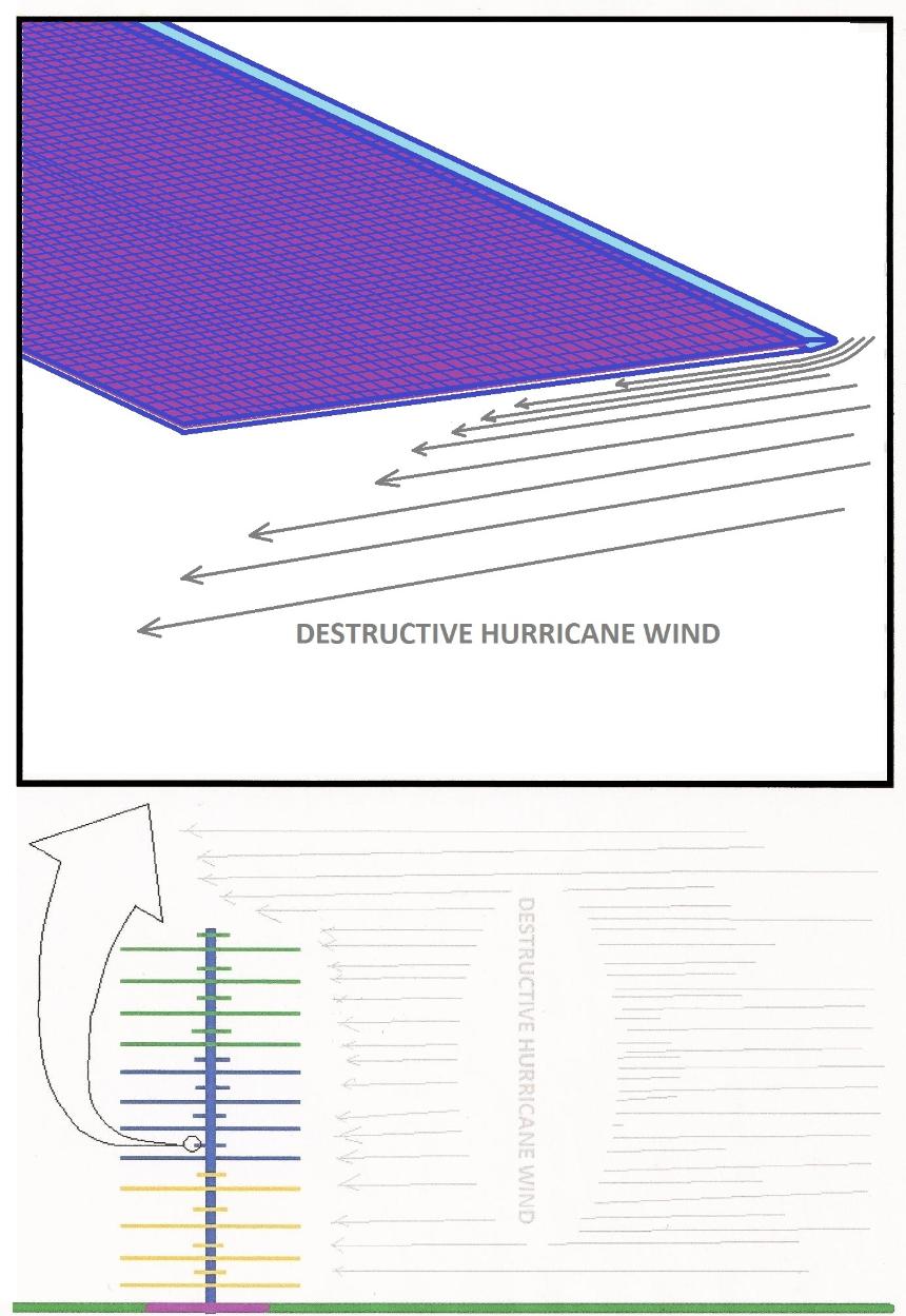
The vertex of the V-type folding blade shall have a pointed form to avoid air resistance. The width of the V-type folding blade shall be designed in accordance with the most efficient or best possible form. A wider V-type folding blade scoops a greater amount of wind force but the other factors related to such wind-harnessing action also need to be carefully considered.
Illustration 12. The Hinge That Gives The Vertex Of The V-Type Folding Blade A Pointed Form
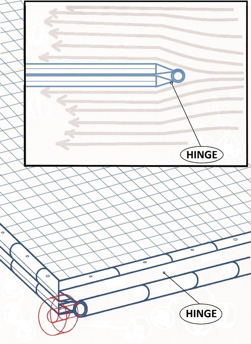
If the V-type folding blades are too long, they may need support at the middle part. To support the lower parts of the V-type folding blades, rods or studs with rotating connections to the edge of these blades may be used. To support the upper parts of the V-type folding blades, rods or studs with rotating connections to the edge of these blades may also be used.
Illustration 12.1. The Use Of Additional Support System At The Middle Part Of The V-Type Folding Blades If Necessary
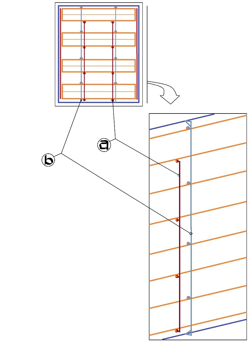
Guide: a) support rod or stud for the lower part of the V-type folding blade, b) support rod or stud for the upper part of the V-type folding blade
One rod/stud may be enough as an additional support for the lower part of the V-type folding blade and one rod/stud may be enough as an additional support for the upper part of the V-type folding blade but more rod/s or stud/s may be added if necessary.
If there is a need for additional hydraulic cylinder/s to close and open the V-type folding blades, hydraulic cylinder/s may also be attached to the support system at the middle part of the V-type folding blades.
Illustration 12.2. The Use Of Additional Hydraulic Cylinder Attached To The Support System At The Middle Part Of The V-Type Folding Blades
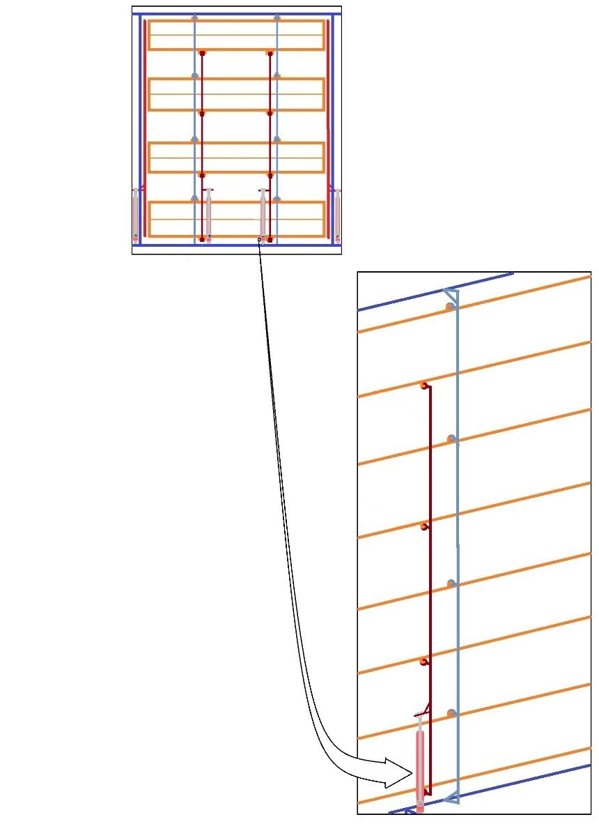
Braking system may be mounted on the pole but it can also be installed in the wheels like a typical brake of a truck and it can be operated through radio control system.
The braking system plays a very important function as a stopper for the turbine in case the computer system and/or the hydraulics system are not able to totally close the blades.
During maintenance, the braking system may be applied even all the blades are already totally closed.
21. Transformers
The transformers for each of the small generators increase the electrical generation then the electricity goes to the power station to further increase the electrical output. If there is surplus of electricity, the electrical energy from this wind power plant is stored in storage facilities and the reserves are used when there is power shortage.
22. Metal Bucket That Is Filled With Oil And Sealed (Optional Part [Warning: If there is a danger of igniting the oil inside the bucket, then there shall be no metal bucket and no oil but a strong flat thick bar or other strong material; and the pole may only touch such base during maintenance when such pole is not remarkably moving.])
If the wheels are designed to carry the whole turbine solely during wind-harnessing action and there is a gap between the pole and the metal bucket, then there is no need for a metal bucket since the purpose of the metal bucket is to contain oil to lubricate the friction between the pole and the metal surface during wind-harnessing action. If the wheels are designed to carry the whole turbine during wind-harnessing action and there is a gap between the pole and the metal bucket, a thick flat metal wider bar that sits on a strong foundation is enough to carry the pole that carries the whole turbine during maintenance when the wheels are removed (However, it may still be safer to put a metal bucket that is filled oil below the pole even if the wheels are the sole carriers of the turbine during wind-harnessing action because there is always a possibility that the wheels may break down and make the bottom of the pole have contact with the metal below and create a destructive friction.).
If the metal bucket is used to carry wholly or partly the weight of the turbine during wind-harnessing action, the pole of the turbine sits on the metal bucket that is filled with oil. The bottom of the metal bucket is thick enough to hold the big and heavy pole; and the metal bucket sits or is mounted on a fortified ground. The use of the metal bucket is also to prevent the destructive downward movement of the pole (If there is no problem on giving the weight of the whole turbine to the metal bucket that is filled with oil during wind-harnessing action, then the said metal bucket that is filled with oil shall be made as the main carrier of the whole turbine during wind-harnessing action [The use of oil inside the bucket is to prevent damage from the friction. The metal bucket needs to be covered and sealed to prevent water from mixing with the oil since water goes at the bottom where there is friction and may cause damage. Drainage screw-hole may also be installed for a regular check and a duct for water that has transparent indicator may also be installed.].).
23. Clutch
Each of the small generators has a clutch that only engages when there is enough torque to run a particular small generator.
When the wind starts to blow remarkably, the turbine turns and accelerates; and also accelerates the turn of the transmission gears and the turn of the long driveshaft where the clutch of each of the small generators are attached by connection gadgets that may use gears or industrial belts (See Illustration 2.). When the torque of the long driveshaft is already in a level that is enough to run one of the small generators, the clutch of the generator for Torque-Level 1 is connected or engaged by hydraulics as being controlled by the computer that uses its control gadgets. When the torque reaches the level that is enough to run another generator, the clutch of the generator for Torque-Level 2 is connected or engaged by hydraulics as being controlled by the computer that uses its control gadgets. When the torque reaches the level that is enough to run another generator, the clutch of the generator for Torque-Level 3 is connected or engaged by hydraulics as being controlled by the computer that uses its control gadgets. This procedure is continued as the torque keeps on increasing until all the small generators are running (This wind power plant may safely operate even during the relatively very strong winds of the hurricane because the automated foldable V-type folding blades of the turbine will just simply close into very sharp angles to elude the excessive wind.).
The particular points where the clutch can be found in the illustrations in this presentation may be modified or removed in accordance with the best possible setting of this wind power plant that uses a giant turbine that is carried by wheels.
Important: All clutches in the whole turbine or site shall be installed in a way that each of the clutches can also be operated manually or by hand in order to facilitate the continuous operation when the hydraulics or other related part malfunctions. In case of manual operation, a person can engage or disengage the particular appropriate clutch upon accurately reading the rounds-per-minute of the appropriate driveshaft. In this scenario, if the rounds-per-minute indicates that the torque of the driveshaft is enough to run another small generator, then it is the time to manually engage the clutch of the next small generator; on the other hand, if the rounds-per-minute indicates that the torque of the driveshaft is no longer enough to run all the currently engaged or running small generators, then it is the time to manually disengage or disconnect the clutch of one of the small generators.
24. Driveshaft
The driveshaft holds the connection gadget that is connected to the clutch of a particular small generator.
OTHER PARTS (NOT REPRESENTED IN ILLUSTRATION 4):
25. Cooling Systems
The absence of cooling system in this wind power plant naturally leads to damage if the turbine is located in a place that is always windy like in the coast because the continuous operation leads to the overheating of the frictionful parts. Fresh water is a good cooler. Water can maintain the lower temperature of the frictionful surfaces by circulation on ducts or pipes connected to the housings or through pouring on the housings. Whenever the turbine works, water can maintain the lower temperature of the frictionful surfaces by continuous circulation through the use of water pumps (The actual surface where there is actual friction shall be lubricated and sealed to prevent the entry of water. The contact between water and any surface where there is friction may lead to overheating and destruction.).
A separate computer that does not ride in the turbine can automate all the cooling systems in one site.
Important: For efficiency, especially to save electricity in running the cooling systems, only the parts that are running remarkably or are threatened by overheating shall be subject to cooling. If a small generator is not running, or if a bearing is not turning, then it is just a waste of electricity to treat them with water. In order to cool only the remarkably-running parts, separate water pumps and separate water lines may be used; and there shall be indicators whenever a part is remarkably running or is threatened by overheating.
25.1. Cooling System For The Bearings
Water can maintain the lower temperature of the frictionful surfaces by circulation on ducts or pipes connected to the housings or through pouring on the housings. Whenever the turbine works, water can maintain the lower temperature of the frictional surfaces by continuous circulation through the use of water pumps (The actual surface where there is actual friction shall be lubricated and sealed to prevent the entry of water. The contact between water and any surface where there is friction may lead to overheating and destruction.).
A separate computer that does not ride in the turbine can automate all the cooling systems in one site.
A cooling system for the bearings like the use of water that automatically passes through ducts or pipes connected to the housings of bearings and circulates whenever the turbine runs may also be used (Computer can automate the whole system even the circulation of water in the ducts or pipes whenever the turbine moves in a "remarkable way" or in a way that can cause heat or overheating.).
There shall be a separate cooling system for the housing of the bearing/s that is on top of the turbine (However, if the water pump at the lower part of the turbine is enough to circulate water in the whole site, this separate cooling system may not be installed.). The said separate cooling system has its own motor, pump, water tank, pipes and ducts that are connected to the metal housing of the bearing/s for the passage of circulating water that continuously gather the heat whenever the turbine turns. The said cooling system is mounted on the beam of the fortification skeleton tower. Whenever the turbine turns, the computer system that is underground can start the said separate cooling system to work by connections that run through the fortification tower (The turning movement of the part of the pole that protrudes on top of the beam of the fortification skeleton tower may also be used to trigger the cooling system to circulate water to the ducts or pipes that are connected to the metal housing of the bearing on top of the turbine.).
25.1.1. Cooling System For The Bearings Of The Wheels
If it is impossible to put water ducts or pipes at the housings of the bearings of the wheels, then the wheels shall be cooled by pouring water on the housings of the bearings. Water may be poured on the housings of the bearings of the wheels either by water spouts that are mounted outside the wheels or by water spouts that ride in the axle-frame of the wheels and supplied with water through a rotating connection between water lines.
Illustration 13. Two Options For The Cooling System For The Bearings Of The Wheels
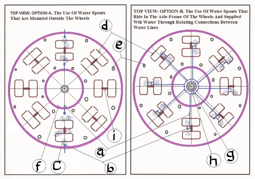
The wheels in one bunch of wheels can be cooled by at least one pair of water spouts that are mounted outside the wheels.
Illustration 14. Small-Scale Cooling System With Water Spouts That Are Mounted Outside The Wheels
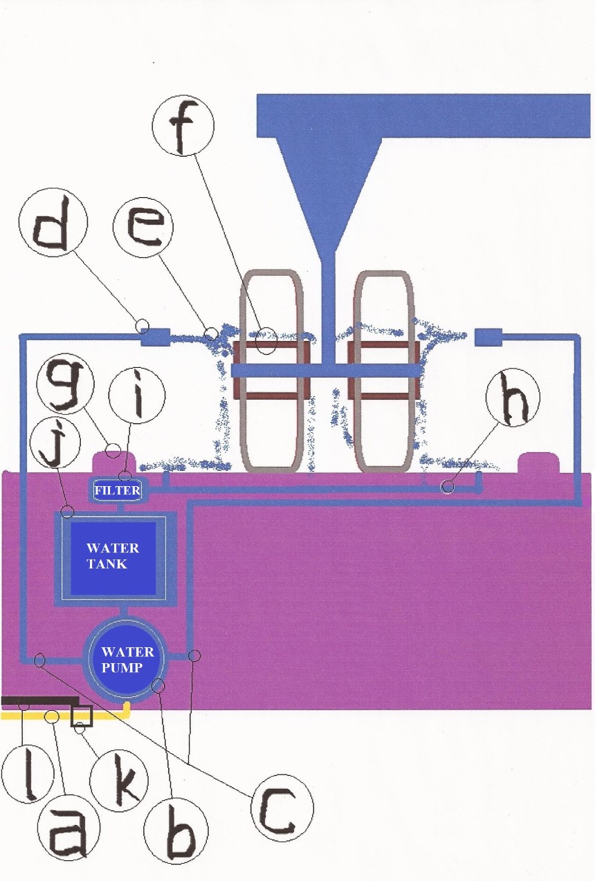
Illustration 15. Large-Scale Cooling System With Water Spouts That Are Mounted Outside The Wheels
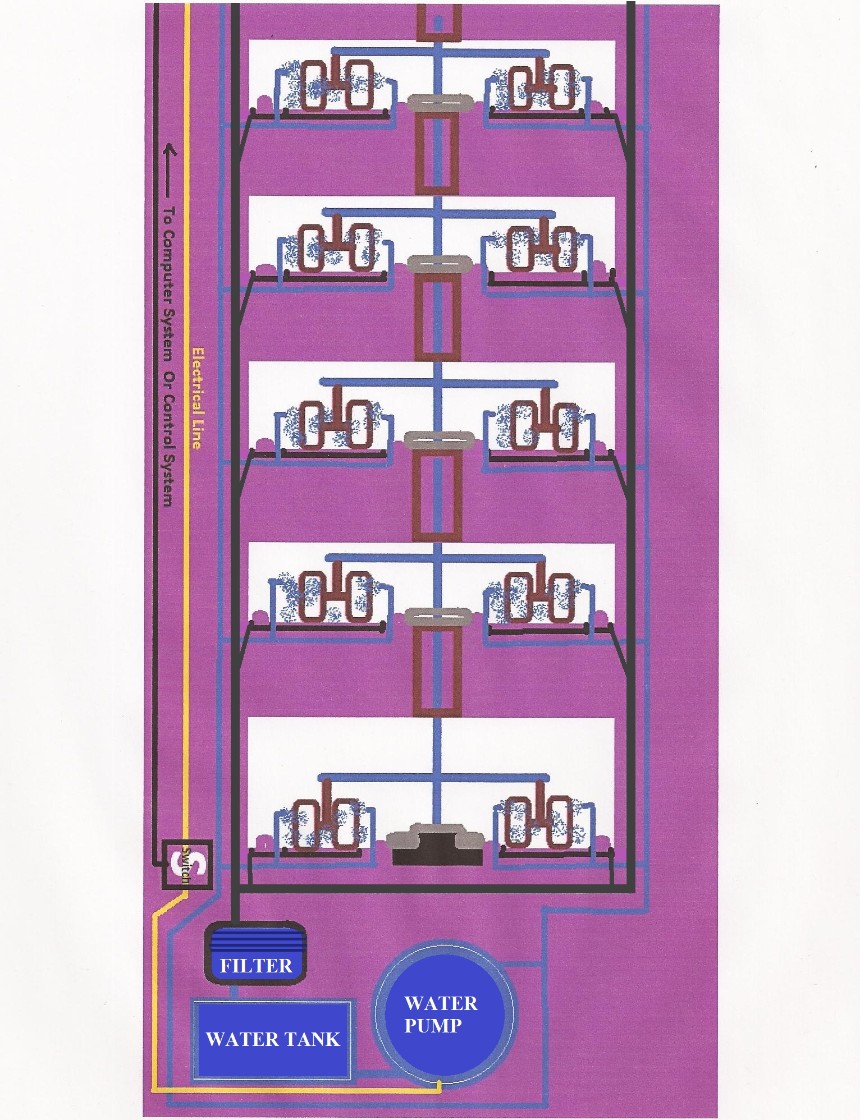
25.1.1.2. Option-B: The Use Of Water Spouts That Ride In The Axle-Frame Of The Wheels And Supplied With Water Through Rotating Connections Between Water Lines
In a situation on the use of water spouts that ride in the axle-frame of the wheels and supplied with water through rotating connections between water lines, every wheel needs at least one water spout.
Illustration 16. Cooling System With Water Spouts That Ride In The Axle-Frame Of The Wheels And Supplied With Water Through Rotating Connections Between Water Lines
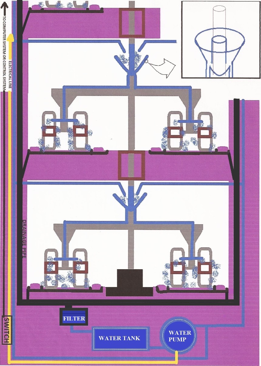
The rotating connection of water lines for the cooling of the housings of the bearings of the wheels shall have the size or form that prevent water from spilling out from such rotating connection of water lines. The rotating connection of water lines may be cone-like or cylindrical.
Illustration 17. Two Forms Of Rotating Connection Of Water Lines For The Cooling Of The Housings Of The Bearings Of The Wheels
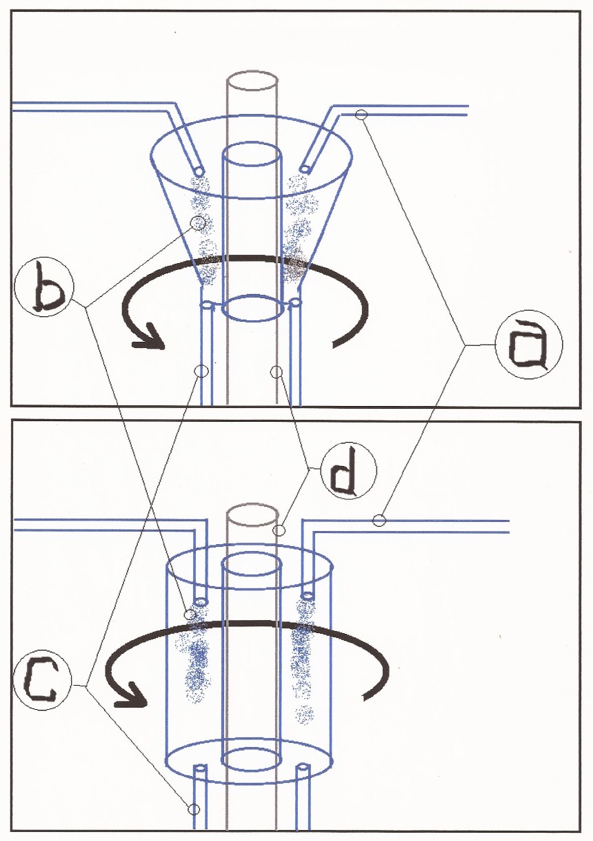
Anything that may exist that has the same efficiency or better than Option-A and Option-B may be used.
25.1.2. Cooling System For The Bearings Of The Pole
The cooling system for the bearings of the pole may use water ducts or pipes and may also use the pouring of water on the housings of the bearings.
25.1.3. Cooling System For The Bearings Of The Long Driveshaft
The cooling system for the bearings of the long driveshaft may use water ducts or pipes and may also use the pouring of water on the housings of the bearings.
25.1.4. Cooling System For Other Bearings (If Any)
Any other bearing that is prone to overheating then destruction needs to have a cooling system.
25.2. Cooling System For The Joint Gears
Water can maintain the lower temperature of the frictionful surfaces by circulation on ducts or pipes connected to the housings or through pouring on the housings. Whenever the turbine works, water can maintain the lower temperature of the frictional surfaces by continuous circulation through the use of water pumps (The actual surface where there is actual friction shall be lubricated and sealed to prevent the entry of water. The contact between water and any surface where there is friction may lead to overheating and destruction.).
A cooling system for the bearings like the use of water that automatically passes through ducts or pipes connected to the housings of bearings and circulates whenever the turbine runs may also be used (Computer can automate the whole system even the circulation of water in the ducts or pipes whenever the turbine moves in a "remarkable way" or in a way that can cause heat or overheating.).
A separate computer that does not ride in the turbine can automate all the cooling systems in one site.
25.3. Cooling System For The Transmission Gears
Water can maintain the lower temperature of the frictionful surfaces by circulation on ducts or pipes connected to the housings or through pouring on the housings. Whenever the turbine works, water can maintain the lower temperature of the frictional surfaces by continuous circulation through the use of water pumps (The actual surface where there is actual friction shall be lubricated and sealed to prevent the entry of water. The contact between water and any surface where there is friction may lead to overheating and destruction.).
A separate computer that does not ride in the turbine can automate all the cooling systems in one site.
A cooling system for the bearings like the use of water that automatically passes through ducts or pipes connected to the housings of bearings and circulates whenever the turbine runs may also be used (Computer can automate the whole system even the circulation of water in the ducts or pipes whenever the turbine moves in a "remarkable way" or in a way that can cause heat or overheating.).
25.4. Cooling System For The Generator
Water can maintain the lower temperature of the frictionful surfaces by circulation on ducts or pipes connected to the housings or through pouring on the housings. Whenever the turbine works, water can maintain the lower temperature of the frictional surfaces by continuous circulation through the use of water pumps (The actual surface where there is actual friction shall be lubricated and sealed to prevent the entry of water. The contact between water and any surface where there is friction may lead to overheating and destruction.).
A separate computer that does not ride in the turbine can automate all the cooling systems in one site.
A cooling system for the bearings like the use of water that automatically passes through ducts or pipes connected to the housings of bearings and circulates whenever the turbine runs may also be used (Computer can automate the whole system even the circulation of water in the ducts or pipes whenever the turbine moves in a "remarkable way" or in a way that can cause heat or overheating.).
25.5. Cooling System For The Metal Bucket That Is Filled With Oil (Optional Part [Warning: If there is a danger of igniting the oil inside the bucket, then there shall be no metal bucket and no oil but a strong flat thick bar or other strong material; and the pole may only touch such base during maintenance when such pole is not remarkably moving.])
Water can maintain the lower temperature of the frictionful surfaces by circulation on ducts or pipes connected to the housings or through pouring on the housings. Whenever the turbine works, water can maintain the lower temperature of the frictional surfaces by continuous circulation through the use of water pumps (The actual surface where there is actual friction shall be lubricated and sealed to prevent the entry of water. The contact between water and any surface where there is friction may lead to overheating and destruction.).
A separate computer that does not ride in the turbine can automate all the cooling systems in one site.
A cooling system for the bearings like the use of water that automatically passes through ducts or pipes connected to the housings of bearings and circulates whenever the turbine runs may also be used (Computer can automate the whole system even the circulation of water in the ducts or pipes whenever the turbine moves in a "remarkable way" or in a way that can cause heat or overheating.).
The cooling system for the metal bucket is not applicable if the pole is designed not to sit on the metal bucket during the wind-harnessing action of the wind turbine or when the wheels are designed to be the sole carrier of all the weights of the wind turbine including the pole during the wind-harnessing action of the wind turbine.).
25.6. Cooling System For Other Overheating-Prone Part/s (If Any)
Water can maintain the lower temperature of the frictionful surfaces by circulation on ducts or pipes connected to the housings or through pouring on the housings. Whenever the turbine works, water can maintain the lower temperature of the frictional surfaces by continuous circulation through the use of water pumps (The actual surface where there is actual friction shall be lubricated and sealed to prevent the entry of water. The contact between water and any surface where there is friction may lead to overheating and destruction.).
A separate computer that does not ride in the turbine can automate all the cooling systems in one site.
26. Indicator For The Angle Of The V-Type Blades
When there is an excessive increase of wind speed due to a storm, the anemometer that rides in the turbine sends the wind speed data to the computer that also rides in the turbine; and such computer calculates the correct angle of the V-type blades that can harness the force that conform to the amount of maintained force in the system. After getting the correct angle, the said computer commands the hydraulic system to close the V-type blades. While closing the V-type folding blades, the indicator reads the angles and continuously sends the data to the said computer. Upon reaching the correct angle, the said computer stops the hydraulic system from closing the V-type folding blades.
26.1. Option-A: By An Indicator For The Actual Synchronized Angle Of The V-Type Blades
The actual synchronized angle of the V-Type blades may be obtained by monitoring only one or two of the V-type blades in the whole turbine.
26.2. Option-B: By An Indicator For The Length Of Protrusion Of The Piston Rod Or Shaft Of The Hydraulic Cylinder
Only one or two among all the hydraulic cylinders in the whole may be monitored to know the changes of angles of the V-type blades in the whole turbine.
The maximum protrusion of the shafts or rods of the hydraulic cylinders may be set to be at the point that is also the fully-closed condition of the V-type folding blades in order to prevent wrecking a related part in case of malfunction of the control system or any related malfunction.
Anything that may exist that has the same efficiency or better than Option-A and Option-B may be used.
27. Compensation Gadget Between Rotating Or Turning Parts With Different Alignments
To compensate with the differences of alignments, universal joints or other compensation gadgets may be used.
28. Indicator To Start The Cooling System For A Particular Part That Is Remarkably Running Or Is Threatened By Overheating
The indicator to start the cooling system for a particular part that is remarkably running or is threatened by overheating is used to facilitate the aim to treat only the part/s that is/are running or the part/s that is/are threatened by overheating. If a specific part is not running or is not threatened by overheating, it is just a waste of electricity to run the cooling system for such part.
28.1. Option-A: The Use The Data On The Rounds-Per-Minute Of The Related Part
The computer can automate the cooling system for a part that is remarkably running or is threatened by overheating by using the data on the rounds-per-minute of the appropriate part.
28.2. Option-B: The Use The Data On The Temperature Of The Related Part
The computer can automate the cooling system for a part that is remarkably running or is threatened by overheating by using the data on the temperature of the appropriate part through the use of a thermometer.
28.3. Other Option (If Any)
Anything that may exist that has the same efficiency or better than Option-A and Option-B may be used.
29. Emergency Switch Located At Every Appropriate Corner Of The Site To Stop All Operations Immediately When Necessary
There shall be emergency switch located at every appropriate corner of the site to stop all operations immediately when necessary. There is always the possibility of danger in the site that may threaten the life of person/s or threaten the facilities.
Once the emergency switch is turned on, all brakes work to stop all operations at the same time and all the V-type folding blades are closed completely (See Illustration 11.). All the braking systems in the whole site that are connected, directly or indirectly, to the turbine shall have a synchronized activity. Also, all the V-type blades have a synchronized activity.
The emergency switch may also be designed to be controlled remotely.
OFFSHORE WIND POWER
The giant turbine can also stand on the ground that is under water like in a beach and the remedy is to simply elevate the location of the metal bucket (Part No. 22) where the pole sits into a safe position that is free from flooding by using strong post/s. The generator may also be put on top of the turbine (The first option is to elevate the position of the metal bucket or Part Number 22 in a level that is free from flooding and the Part Numbers 12, 13, 14, 21, 23, and 24 are in the same position as shown in Illustration 4. The second option is to elevate the position of the metal bucket or Part Number 22 in a level that is free from flooding and put the Part Numbers 12, 13, 14, 21, 23, and 24 on the level that is on top of the turbine as a modification; and most of the weight shall be put on top of the fortification skeleton tower.). If the metal bucket (Par No. 22) is elevated above the flooded ground level in the sea, strong metal platform may be used in place of the fortified ground (Part No. 11) as shown in Illustration 4 (If the wind turbine is designed to have no metal bucket like in the case that all the weights are completely carried by wheels during wind-harnessing operation, the flat metal bar that replaced the metal bucket may be as low as the water level.).
Illustration 18. Conceptual Offshore Version Of The Giant Wind Turbine That Is Carried By Wheels With Only Three Layers (More Layers May Be Added.)
.jpg.opt860x1725o0,0s860x1725.jpg)
The offshore wind turbine may also be carried by a floating pointed cylindrical buoy instead of wheels.
Illustration 19. The Use Of Floating Pointed Cylindrical Buoy Instead Of Wheels
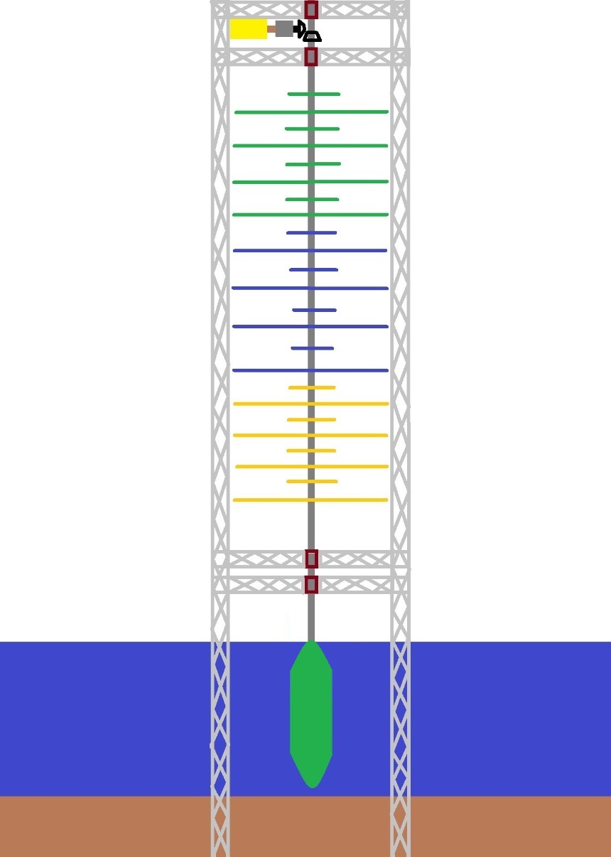
The size or the diameter-height proportion of the buoy and the form of all other parts in this illustration are conceptual. The diameter-height proportion of the buoy and the form of all other parts shall be in the perfect form (that considers leverage, depth of water, wave force, and other things) for the most efficient condition of the turbine.
The purpose of the pointed design of the cylindrical buoy is to elude shocking force of seawater.
The pole needs to have a stopper to prevent its possible vertical movement because of wave or tidal force.
To facilitate the easier installation of the turbine, the pointed cylindrical buoy that carries the turbine may be filled with water to sink it in order to avoid its upward force when installing; then simply pump out the water from the buoy and replace it with air when the installment of the turbine is already complete (The buoyant force shall be enough to carry the whole turbine and shall not be excessive to avoid damaging the stopper that stops the pole from vertical movement [The anti-upward-movement stopper and the anti-downward-movement stopper may also use bearings and shall be free from water. The stoppers may also be installed on the upper part of the turbine.].). The buoy needs to have a good piping system for the entry and exit of water as well as for the entry and exit of air (Another option is the use of air pressure to push the water out from the opening at the bottom part of the buoy; and water can go back inside the buoy when the pressure is released. This operates like a submarine.).
Illustration 19.1. Stopper At The Upper Part Of The Buoy-Carried Turbine To Prevent Upward Or Downward Movement
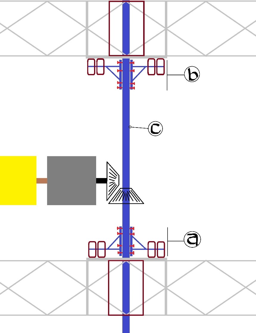
Guide: a) anti-downward-movement stopper, b) anti-upward-movement stopper, c) pole or axis of the turbine
If the offshore area is too deep, the fortified skeleton towers may also be mounted on big and strong floating bodies and the wind turbine may be carried by a floating pointed cylindrical buoy.
Illustration 20. Totally Floating Offshore Version Of The Giant Wind Turbine That Is Carried By Floating Pointed Cylindrical Buoy Instead Of Wheels With Only Three Layers (More Layers May Be Added By Enlarging The Carrier.)
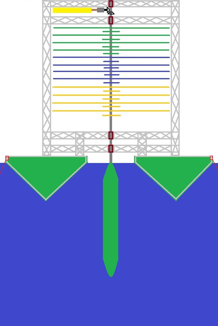
The size or the diameter-height proportion of the buoy and the form of all other parts in this illustration are conceptual. The diameter-height proportion of the buoy and the form of all other parts shall be in the perfect form (that considers leverage, depth of water, wave force, and other things) for the most efficient condition of the turbine.
In the totally floating offshore version, the giant wind turbines may also be carried by wheels that run on platforms that are carried by anchored floating carriers.
Illustration 21. Totally Floating Offshore Version Of The Giant Wind Turbine That Is Carried By Wheels With Only Three Layers (More Layers May Be Added By Enlarging The Carrier.)
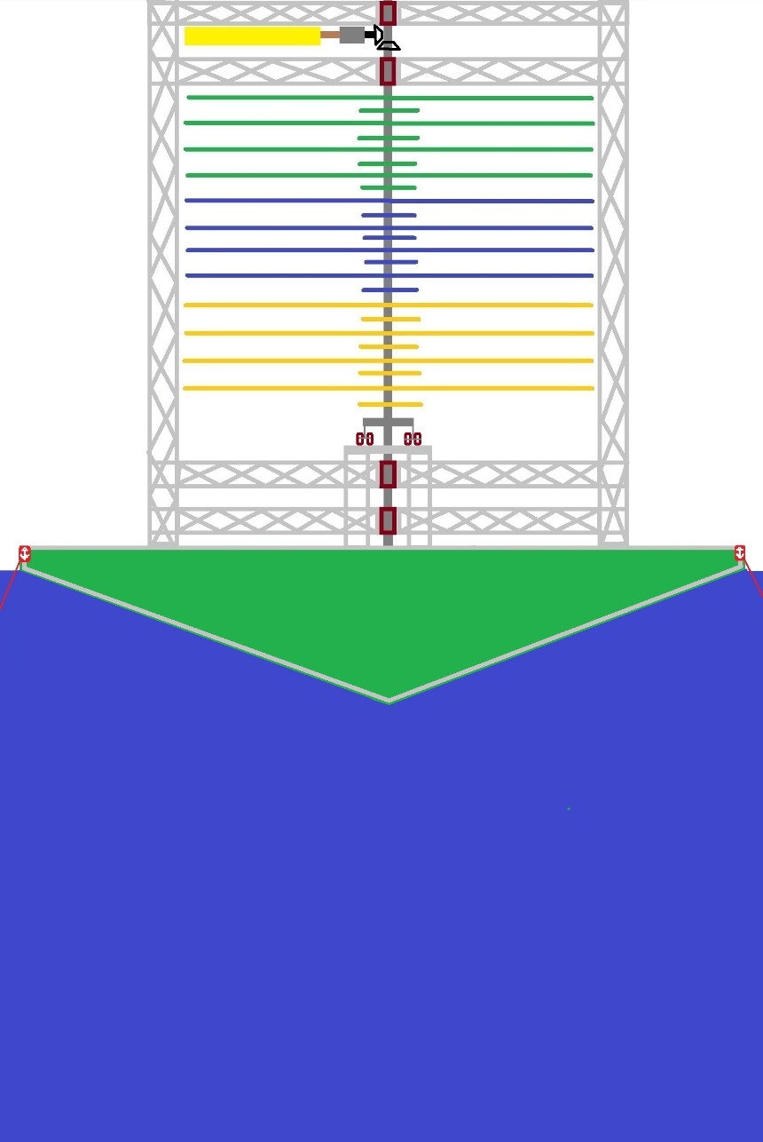
The size, form, and proportion of all parts in this illustration are conceptual. The size, form, and proportion of all parts shall be in the perfect form for the most efficient condition of the turbine.
Wheels may also be combined with buoy in carrying the weight of the turbine.
Illustration 22. Totally Floating Offshore Version Of The Giant Wind Turbine That Is Carried By Combined Wheels And Buoy With Only Three Layers (More Layers May Be Added By Enlarging The Carrier.)
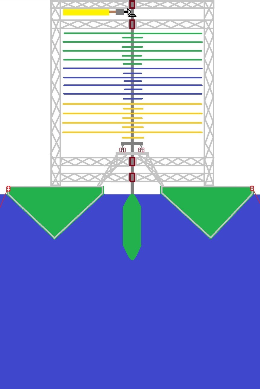
The size or the diameter-height proportion of the buoy and the form of all other parts in this illustration are conceptual. The diameter-height proportion of the buoy and the form of all other parts shall be in the perfect form (that considers leverage, depth of water, wave force, and other things) for the most efficient condition of the turbine.
In the shallow-water area where there is a need to build fortification skeleton towers founded on the ground underwater, the combination of wheels and buoys may also be used if the water level is enough.
The materials for the fortification skeleton tower that is in contact with salt water shall be protected from corrosion.
Illustration 23. Shallow-Water Version Of The Giant Wind Turbine That Is Carried By Combined Wheels And Buoy With Only Three Layers (More Layers May Be Added By Enlarging The Carrier.)
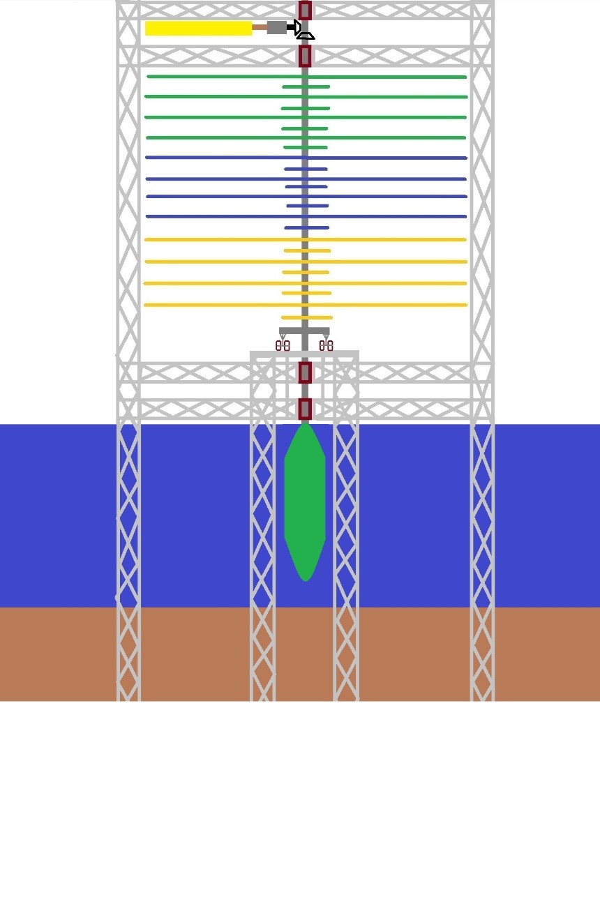
The size or the diameter-height proportion of the buoy and the form of all other parts in this illustration are conceptual. The diameter-height proportion of the buoy and the form of all other parts shall be in the perfect form (that considers leverage, depth of water, wave force, and other things) for the most efficient condition of the turbine.
THE USE OF BUOY THAT FLOATS ON A FLOODED DRY DOCK TO CARRY THE TURBINE INSTEAD OF WHEELS IN THE MAINLAND
A form that may have a remarkable advantage over the use of wheels in carrying the weight of the mainland wind turbine is the one that uses buoy that floats on a flooded dry dock because a buoy does not require a cooling system unlike the wheels that may burn without the cooling system and a smooth perfect cylinder buoy may also have a lesser resisting friction if it turns on the water as compared to the wheel that has frictionful bearings. Another possible advantage of the buoy over the wheel is its longer life span as long as corrosion is prevented by painting the buoy because the buoy has no metal-scratching action with the water where it floats and turns.
The shape of the dry dock may also be cylindrical, which is in conformity with the cylindrical shape of the buoy, to save construction materials. The spin of the water may also accelerate if the dry dock is a perfect cylinder.
Also, the possible upward or downward movement of the pole may be prevented by using stoppers (See Illustration 19.1.).
Illustration 24. The Use Of Buoy That Floats On A Flooded Dry Dock To Carry The Turbine Instead Of Wheels In The Mainland
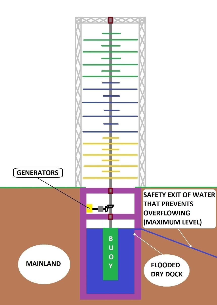
The size or the diameter-height proportion of the buoy and the form of all other parts in this illustration are conceptual. The diameter-height proportion of the buoy and the form of all other parts shall be in the perfect form (that considers leverage, volume of water, and other things) for the most efficient condition of the turbine.
The use of movable transmission gadgets (such as sliding gears, universal joints, or others [if any]) without using the anti-upward-movement-stopper and anti-downward-movement-stopper may also be better because it avoids putting the very heavy weight of the pole that carries the weight of the whole turbine into a destroyable parts like the wheels of the said stoppers, which may easily destroy such stoppers despite their sizes and strength.
Illustration 25a. The Use Of Sliding Gears In The Movable Transmission Gadget
If the “dry dock” has no water, the strong base of the buoy that has the base of the pole that runs through the center of the buoy sits on the strong base of the dry dock.
Illustration 25b. The Use Of Universal Joint In The Movable Transmission Gadget
If the “dry dock” has no water, the strong base of the buoy that has the base of the pole that runs through the center of the buoy sits on the strong base of the dry dock.
Important: There shall be a warning alarm if the base of the turning buoy is already remarkably close to the base of the “dry dock” in order to make a manual or automatic braking or adjustment operation in order to avoid scratching the base of the buoy that may lead to damage or destruction.
To facilitate the utilization of the slow wind-speed in a manner that collects the force in many areas or scoops then concentrating it into a tiny spot that is the small generator (that has a similarity with using a magnifying lens to focus the sunlight into one tiny spot), a high-speed transmission is necessary. In relation to this, the use of the timing belt or other related gadgets that uses very large circular gear may be used.
Illustration 26. The Use Of Timing Belt Or Other Related Gadgets For A High Speed Transmission
This wind power plant, in any of its model or version, shall be in its perfect form and condition.
* The ideal location for this wind power plant is the place that is away from homes but in case it is placed near houses, there is zero-noise from the gears and generators if they are sealed underground; only the outer parts of the wind turbine may be heard.
* This wind power plant does not kill birds and bats because the turbine is slow-moving since the speed is in the transmission gears and in the generator.
* This wind power plant does not need to occupy wide landscapes in order to produce a particular related great amount of electricity because the height can be increased like the very tall buildings.
* This wind power plant may be lower cost because it may use polyethylene plastic sheets, timber, and other cheaper things like the parts that may be similar to the parts of the lower-cost trucks, machines, construction materials, and others; and it may also use recycled materials.
* This wind power plant eludes the destructive hurricane force since the V-type folding blades/frames automatically close into lying-flat horizontal position through hydraulics and computers when there is excessive wind force and automatically open when the wind becomes weak.
*This wind power plant is free from fire because it has an efficient cooling system and efficient prevention of excessive force.
*This wind power plant produces electricity even in weaker wind because it uses small generators that are sequentially engaged and disengaged by computer through gadgets depending on the torque levels.
* This wind power plant helps the wind-energy companies because it is free for all.
____________________EVERY PERSON SHALL BE FREE TO BUILD AND USE THIS WIND POWER PLANT.____________________
Warning: If the claim of ownership of the technology in this wind power plant, which is described as the use of a giant vertical-axis wind turbine that is carried by wheels, and/or buoys, and uses automatically closing and opening V-type folding blades/frames that are arranged into equally divided angles of the different layers of clusters of blades/frames and uses small generators that are sequentially engaged and disengaged by computer through gadgets depending on the torque levels, is equal to claiming the ownership of the document presented in the other websites of this source, then no person shall be allowed to claim the ownership of the said technology since the claim of ownership of the aforesaid document is a serious offense as cited in the fourth paragraph of Part 3 of the aforementioned document that can be found in the succeeding websites.
Websites: http://balancedway.weebly.com/ , http://www.youfreeweb.com/balancedway/ , http://www.YouFreeWeb.com/balancedway2, http://www.YouFreeWeb.com/balancedway3 , http://www.YouFreeWeb.com/balancedway4, http://balancedway2.weebly.com/ , http://balancedway3.weebly.com/ , http://balancedway4.weebly.com/<?
or
http://balancedway.yolasite.com/ , http://balancedway1.yolasite.com/ , http://balanceddiet.yolasite.com/
, http://balanceddiet1.yolasite.com/
(See Figure 4, Figure 521, Figure 6, Figure 7, Figure 8, Figure 9, Figure 10, Figure 1021, and
Figure 1022 at http://figure4etc.yolasite.com/ , http://figure4etc1.yolasite.com/ , http://figure4etc2.yolasite.com/
, or http://figure4etc3.yolasite.com/ .)
See Announcements at http://announcements-balancedway.weebly.com , http://announcements-balancedway.yolasite.com/
, or http://www.YouFreeWeb.com/announcements-balancedway , http://www.wix.com/balancedwaybalancedw/announcements-balancedway
YouTube: Visit TheServiceWeb's Channel (Warning: TheServiceWeb is not an author for this document and it is a serious offense to claim the authorship of the book presented in the preceding websites; and this serious offense is cited in the fourth paragraph of PART 3 of the said book. Any impostor that appears as TheServiceWeb claims to be the internet. There is no website with its corresponding video that was, and to be, published or uploaded by TheServiceWeb other than the following websites with their respective videos: 1. http://www.youtube.com/watch?v=W1FBbFEmiek [AFRICA DROUGHTS IRRIGATION - WIND POWER PLANT WITH COLOSSAL TURBINE THAT HAS WHEELS ....], 2. http://www.youtube.com/watch?v=Ks1CvPo-Wf4 [{B - 1 of 3} The Genuine Content Of figure4etc yolasite com , etc {Part 1 of 3}], 3. http://www.youtube.com/watch?v=yl6tnWF9Bns [{B - 2 of 3} The Genuine Content Of figure4etc yolasite com , etc {Part 2 of 3}], 4. http://www.youtube.com/watch?v=Ceo_vgVg4LI [{B - 3 of 3} The Genuine Content Of figure4etc yolasite com , etc {Part 3 of 3}], 5. http://www.youtube.com/watch?v=gRlgksM3PwM [{A - 1 of 20} The Genuine Content Of balancedway yolasite com , etc {Part 1 of 20}], 6. http://www.youtube.com/watch?v=-pjdQ2Otu_U [{A - 2 of 20} The Genuine Content Of balancedway yolasite com , etc {Part 2 of 20}], 7. http://www.youtube.com/watch?v=1stwP--vkM4 [{A - 3 of 20} The Genuine Content Of balancedway yolasite com , etc {Part 3 of 20}], 8. http://www.youtube.com/watch?v=11Oa5bd995A [{A - 4 of 20} The Genuine Content Of balancedway yolasite com , etc {Part 4 of 20}], 9. http://www.youtube.com/watch?v=KtuOY5LL-_s [{A - 5 of 20} The Genuine Content Of balancedway yolasite com , etc {Part 5 of 20}], 10. http://www.youtube.com/watch?v=JtZ0IN9TcmM [{A - 6 of 20} The Genuine Content Of balancedway yolasite com , etc {Part 6 of 20}], 11. http://www.youtube.com/watch?v=nuWuhnTo7wk [{A - 7 of 20} The Genuine Content Of balancedway yolasite com , etc {Part 7 of 20}], 12. http://www.youtube.com/watch?v=Za22omycR70 [{A - 8 of 20} The Genuine Content Of balancedway yolasite com , etc {Part 8 of 20}, 13. http://www.youtube.com/watch?v=Ez3YKWn5jQs [{A - 9 of 20} The Genuine Content Of balancedway yolasite com , etc {Part 9 of 20}], 14. http://www.youtube.com/watch?v=zXAxUwPtbSc [{A - 10 of 20} The Genuine Content Of balancedway yolasite com , etc {Part 10 of 20}, 15. http://www.youtube.com/watch?v=ZvdppRk8OOk {A - 11 of 20} The Genuine Content Of balancedway yolasite com , etc {Part 11 of 20}], 16. http://www.youtube.com/watch?v=trEnJ5Fhzjs [{A - 12 of 20} The Genuine Content Of balancedway yolasite com , etc {Part 12 of 20}], 17. http://www.youtube.com/watch?v=eteS-JWRo7s [{A - 13 of 20} The Genuine Content Of balancedway yolasite com , etc {Part 13 of 20}, 18. http://www.youtube.com/watch?v=30o28CzOnr4 [{A - 14 of 20} The Genuine Content Of balancedway yolasite com , etc {Part 14 of 20}], 19. http://www.youtube.com/watch?v=yPGeEIJcllI [{A - 15 of 20} The Genuine Content Of balancedway yolasite com , etc {Part 15 of 20}], 20. http://www.youtube.com/watch?v=4op9JYhjOo4 [{A - 16 of 20} The Genuine Content Of balancedway yolasite com , etc {Part 16 of 20}], 21. http://www.youtube.com/watch?v=cuwOGIf5lgk [{A - 17 of 20} The Genuine Content Of balancedway yolasite com , etc {Part 17 of 20}], 22. http://www.youtube.com/watch?v=niMP3QkewV4 [{A - 18 of 20} The Genuine Content Of balancedway yolasite com , etc {Part 18 of 20}], 23. http://www.youtube.com/watch?v=X_B4JHgoQzA [{A - 19 of 20} The Genuine Content Of balancedway yolasite com , etc {Part 19 of 20}], 24. http://www.youtube.com/watch?v=h0WNOwBMARQ [{A - 20 of 20} The Genuine Content Of balancedway yolasite com , etc {Part 20 of 20}], 25. http://www.youtube.com/watch?v=mlb-kq5UzBU AFRICA DROUGHTS [A THEORETICAL IRRIGATION SYSTEM FOR A DROUGHT-PRONE COUNTRY], 26. http://www.youtube.com/watch?v=xMo7Me34GFw WIND POWER PLANT [THEORETICAL POWER PLANT TO RUN IRRIGATION AND OTHERS 3], 27. http://www.youtube.com/watch?v=c4BmJjQzo24 AGRICULTURE IN DROUGHTS [THEORETICAL POWER PLANT TO RUN IRRIGATION AND OTHERS 4], 28. http://www.youtube.com/watch?v=r3ljM7Gw64I AFRICA DROUGHTS [THEORETICAL POWER PLANT TO RUN IRRIGATION AND OTHERS 2], and 29. http://www.youtube.com/watch?v=-BsuzyDMSr0 AFRICA IRRIGATION [THEORETICAL POWER PLANT TO RUN IRRIGATION AND OTHERS 1]. Anything that does not belong to the list is from an impostor that claims to be the internet. Also, the annotations or descriptions in the aforesaid twenty nine [29] videos only tell about the perfection of construction, maintenance, improvement, and safety on the presented irrigation system and power plant as well as the last revision of the book in which the very few changes are noted in all the websites of the said book except Yola; and any annotation or description that does not conform to the said topic is created by an impostor or hacker that hacked the website/s or e-mail address/es.).
__________________________________________________________________________________________________________________________________